
Reverse barb system for screws and nails

Inactive Publication Date: 2006-06-20
FRENCH DOUGLAS R
View PDF20 Cites 67 Cited by
  • Summary
  • Abstract
  • Description
  • Claims
  • Application Information

AI Technical Summary

Benefits of technology

[0014]Accordingly, it is a principal object of the invention to provide a reverse barb system for screws and nails to improve the resistance of screw and nail type fasteners to backing out.
[0015]It is another object of the invention to provide a reverse barb system for screws that increases the screw's resistance to turning out.
[0016]It is a further object of the invention to provide a reverse barb system for nails that increases the nail's resistance to backing out.
[0017]Still another object of the invention is to provide a reverse barb system for nails that causes the nail to turn slightly as it is driven.
[0018]It is an object of the invention to provide improved elements and arrangements thereof for the purposes described which is inexpensive, dependable and fully effective in accomplishing its intended purposes.

Problems solved by technology

A problem exists in construction wherein the fasteners used in wood frame construction, particularly screws and nails, tend to come loose over time.
Subjected to weight, expansion and contraction of materials due to changing temperature and humidity, vibration, the force of storms, and other stresses, the screws and nails used to join wood and other materials in construction have a tendency to back out.
As the screws and nails back out, the joints that they fasten become loose, leaving structures weak and vulnerable to further damage, or even collapse.
However, the barbs are quite small relative to the cross section of the fastener.
Although wood fibers will tend to return to their original position after the fastener is driven into place, they are not likely to fully close in behind the barbs.
Again, however, the barbs cannot have their full gripping effect when they will back out along the same path through which they were inserted.
This fastener, however, lacks a sharp point.
This method of manufacture of the fastener is not suitable for nails, which are typically formed by a cold-forge process.
While effective for its purpose of fastening trim pieces to a wall construction of wallboard and metal studs, the flexible barbs of the barbed finish nail are not useful as a general-purpose construction nail.

Method used


Image

  • Reverse barb system for screws and nails
  • Reverse barb system for screws and nails
  • Reverse barb system for screws and nails

Examples


Embodiment Construction

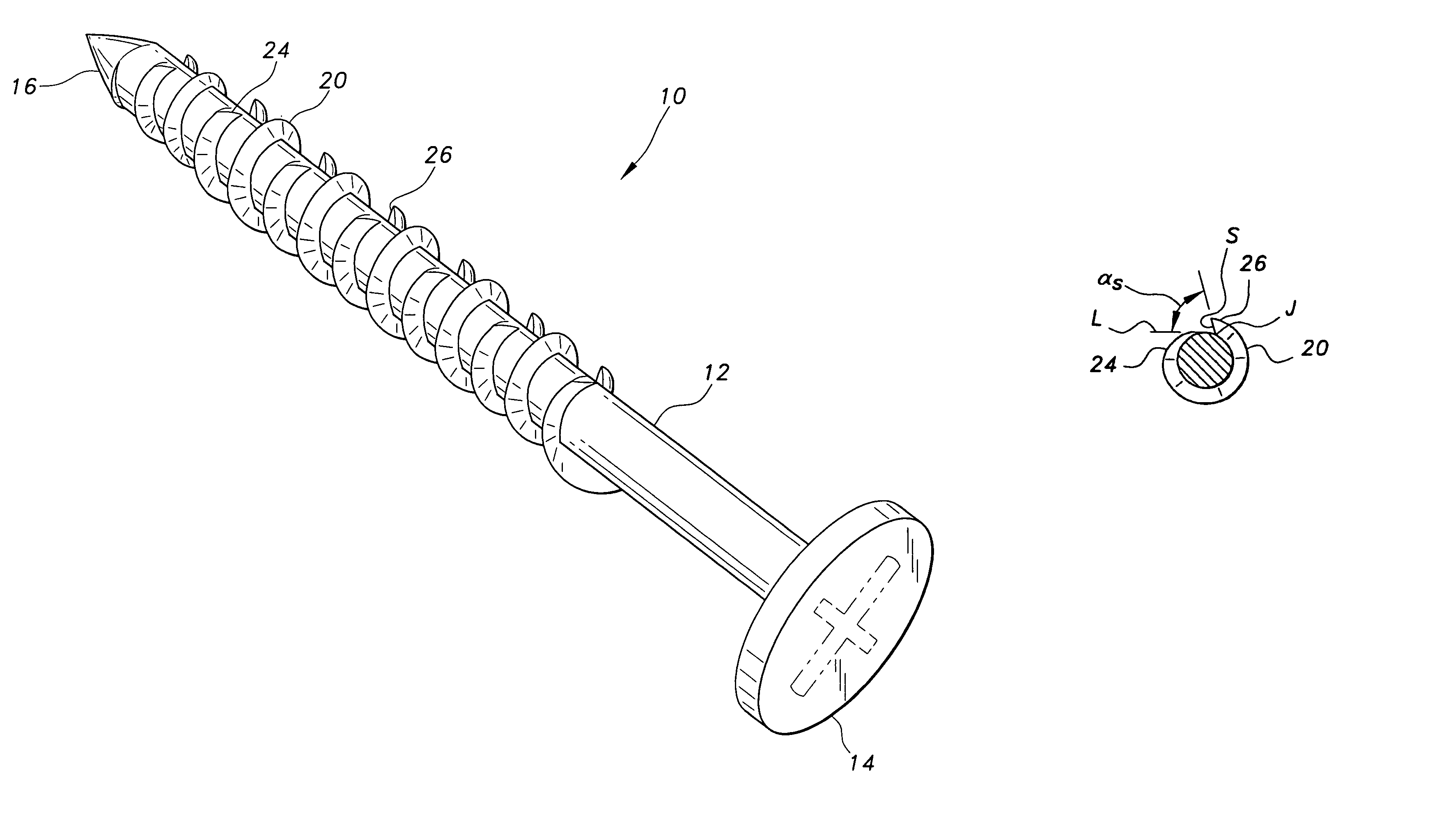
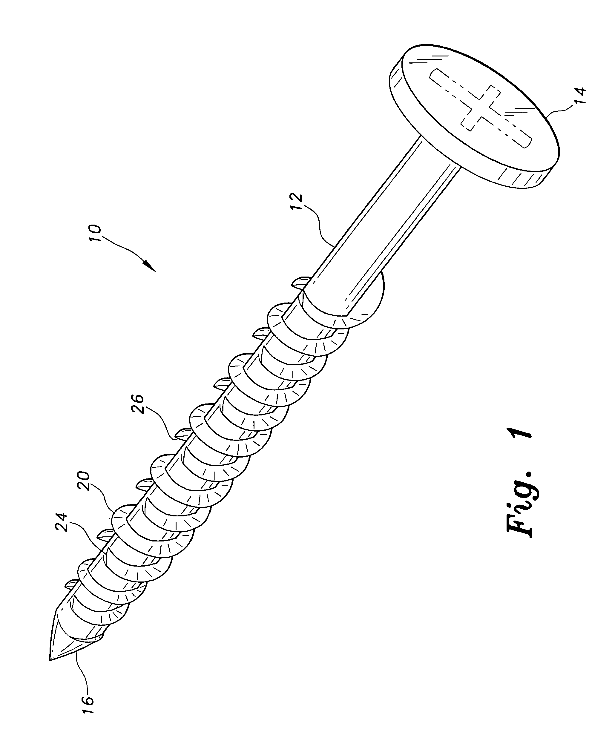
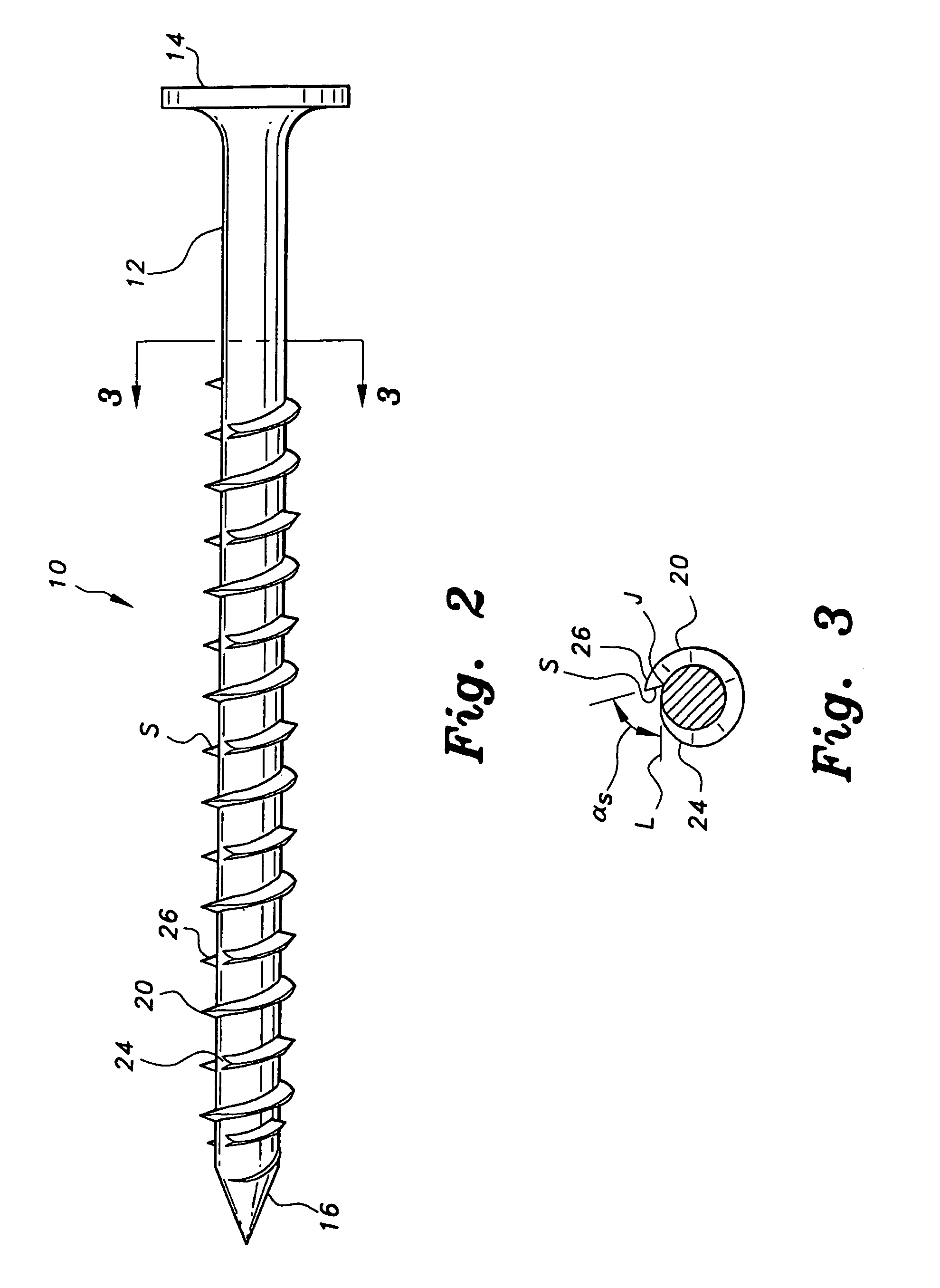
[0031]The present invention is a reverse barb system for screws and nails. Barbed fasteners according to the invention resist backing out once driven into a work piece or construction material such as wood. The reverse barb system for screws and nails includes a screw with barbed threads, designated generally as 10 in the drawings and shown particularly in FIGS. 1–3, and a nail with a barbed point designated generally as 30 and shown particularly in FIGS. 7–10.

[0032]Turning to FIG. 1, the screw with barbed threads 10 is a screw generally in the form of conventional screws, having an elongated shank 12 with a head end 14 and a point end 16. A thread is formed on the outer periphery of the shank 12. However, rather than a conventional continuous thread, the thread is composed of several barbed thread sections 20. Each barbed thread section 20 is a section of thread having a leading edge 24 and a trailing edge 26. As shown in the figures, each barbed thread section 20 extends 720° arou...


PUM

PropertyMeasurementUnit
Angleaaaaaaaaaa
Angleaaaaaaaaaa
Angleaaaaaaaaaa

Abstract

The reverse barb system for screws and nails includes fasteners that are barbed to prevent backing out once driven into a workpiece or construction material, such as wood. A screw with barbed threads has several barbed thread sections. Each barbed thread section is a section of thread having a leading edge and a trailing edge, the trailing edge defining a barb to increase the screw's resistance to backing out once driven into place. A nail with a barbed point is a nail having one or more barbs formed in the nail's point. Each barb is defined by a leading edge and a trailing edge. The barb's trailing edge forms an acute angle with the longitudinal axis of the nail. The barbs extend from the nail shank to prevent the nail from backing out.

Description

CROSS-REFERENCE TO RELATED APPLICATION[0001]This application claims the benefit of U.S. Provisional Patent Application Ser. No. 60 / 477,479, filed Jun. 11, 2003.BACKGROUND OF THE INVENTION[0002]1. Field of the Invention[0003]The present invention relates to nail and screw type fasteners. More specifically, the invention is a reverse barb system for screws and nails that provides screws and nails with a resistance to backing out or popping out from a workpiece.[0004]2. Description of the Related Art[0005]A problem exists in construction wherein the fasteners used in wood frame construction, particularly screws and nails, tend to come loose over time. Subjected to weight, expansion and contraction of materials due to changing temperature and humidity, vibration, the force of storms, and other stresses, the screws and nails used to join wood and other materials in construction have a tendency to back out. Nails simply work back out as if pulled out, while screws tend to turn out over ti...

Claims


Application Information

Patent Timeline
IPC IPC(8): F16B25/10F16B35/04F16B15/06F16B25/00F16B33/02
CPCF16B15/06F16B25/0015F16B25/0089F16B25/0068F16B25/0052
Inventor FRENCH, DOUGLAS R.
Owner FRENCH DOUGLAS R
Learn More