Compliant chain guide with blade spring

a technology of chain guide and blade spring, which is applied in the direction of belt/chain/gearing, machine/engine, machine/engine, etc., can solve the problems of chain tension being considerably different, the character of the chain system tends to change, and the engine system is poor or even damaged, so as to improve the chain performance, improve the drive behavior, and reduce the cost of design.

Active Publication Date: 2006-06-20
BORGWARNER INC
View PDF18 Cites 12 Cited by
  • Summary
  • Abstract
  • Description
  • Claims
  • Application Information

AI Technical Summary

Benefits of technology

[0007]A slightly non-rigid or non-stationary compliant chain guide is provided for improved drive behavior.
[0008]A compliant chain guide disposed to being used in short-center distance drives is provided. This chain guide possesses low cost in design and can improve chain performance, especially on certain short-center distance drives.
[0009]In the present invention, a slight amount of travel is provided for the compliance of the guide and for force-reduction, but not for the purpose of maintaining tension upon the chain. One distinguishing feature between the present guide and that of a tensioner arm is that the total travel length of a tensioner arm can be significantly greater than that of the guide in the present invention. In other words, the present invention is not intended to function as a tensioner in that it cannot take up large amounts of slack. Rather, the compliance is meant to dampen out impacts and transverse vibrations that can affect chain control, guide wear, and bracket fatigue. One of the beneficial results the compliant chain guide is a low cost design which can improve chain performance, especially on certain short-center distance drives.
[0010]A chain guide that has an elastic member, a wear face, and possibly some kind of mounting bracket or support fixture is provided. The elastic member is captured therein. The wear face has an inside and outside surface. The outside surface is disposed to contact a chain. The inside surface is in contact with the elastic member. Through the motion of the elastic member, the chain guide absorbs and dampens out impacts and transverse vibrations, both of which can affect chain control, guide wear, and bracket fatigue.

Problems solved by technology

Over the operating life time of a chain system such as an engine timing chain system, the characteristic of the chain system tends to alter.
Prevention of slippage is especially important in the case of a chain driven camshaft in an internal combustion engine because slippage may alter the camshaft timing by several degrees, possibly causing poor performance or even damage to an engine system.
Furthermore, camshaft and crankshaft induced torsional vibrations cause chain tension to vary considerably.
This tension variation results in chain elongation.
Moreover, wear of the chain components during prolonged use can cause permanent elongation of the chain that results in a decrease in the tension of the chain.

Method used


Image

  • Compliant chain guide with blade spring
  • Compliant chain guide with blade spring
  • Compliant chain guide with blade spring

Examples


Embodiment Construction

[0013]This section includes the descriptions of the present invention including the preferred embodiment of the present invention for the understanding of the same. It is noted that the embodiments are merely describing the invention. The claims section of the present invention defines the boundaries of the property right conferred by law.

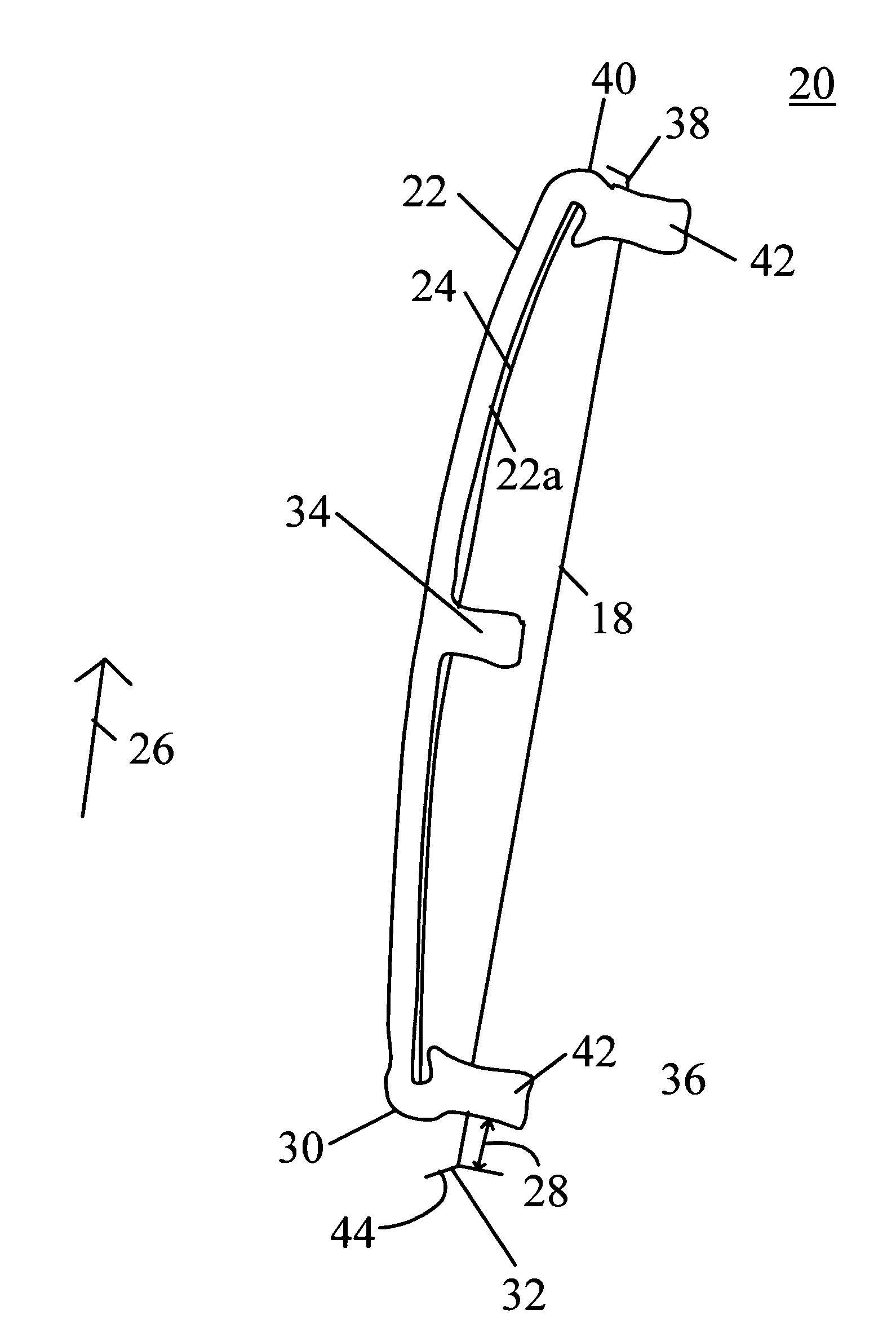
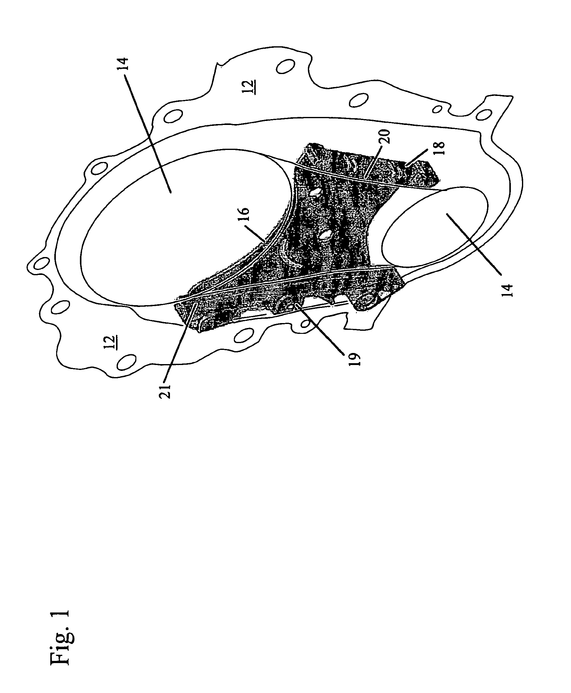
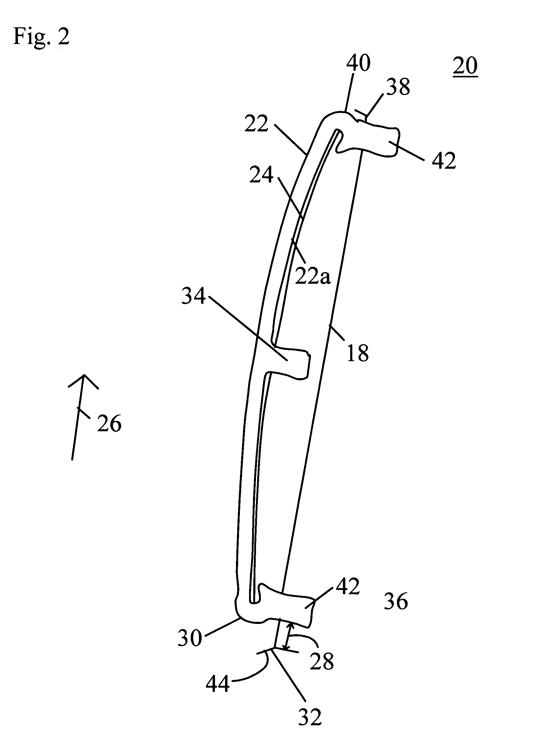
[0014]Referring to FIGS. 1 and 2, a preferred embodiment of the present invention is shown. An engine front cover 12 is provided and an inside view is shown. Front cover 12 has a pair of locations 14 for accommodating both a driving gear and a driven gear (both not shown). An endless chain (also not shown) is disposed to connect and engage both the driving gear and the driven gear. Bracket 16 is suitably affixed upon front cover 12. Bracket 16 has a first flange 18 and a second flange 19. First flange 18 is disposed to have a chain guide device 20 mounted thereon; and second flange 19 is disposed to have a tensioner system 21 mounted thereon.

[0015]...


PUM


Abstract

A chain guide has an elastic member and a wear face. The wear face has the elastic member captured therein. The wear face has an inside surface and an outside surface. The first surface is disposed to contact a chain. The other surface is in contact with the elastic member. Through the compliance of the wear face and the elastic member, the chain guide absorbs some degree of impacts and transverse vibrations, both of which can affect chain control, guide wear, and bracket fatigue.

Description

FIELD OF THE INVENTION[0001]The invention pertains to the field of chain guides in chain drives. More particularly, the invention pertains to a compliant chain guide with a blade spring. The preferred embodiment of the present invention is for use in engine timing systems.BACKGROUND OF THE INVENTION[0002]The use of chain guides is known in the art. A chain guide is also known as a stationary arm, which is stationary in relation to a moving endless chain, thereby guiding the chain along a desired path and preventing unwanted side-to-side motions. Typically, a chain guide works in conjunction with a chain tensioner that takes up excess slack to keep the endless chain in a desired tensioned state.[0003]U.S. Pat. No. 6,447,414, which is hereby incorporated herein by reference teaches a chain tensioner system having a hydraulic tensioner and a tensioner arm with a spring blade. A hydraulic tensioner applies force against the end of the tensioner arm. The arm is pivotally supported at one...

Claims


Application Information

Patent Timeline
Patent Type & Authority Patents(United States)
IPC IPC(8): F16H7/08F16H7/18
CPCF16H7/18F16H7/0838F16H2007/0874F16H2007/0804F02B67/06
Inventor GARCIA, MARIANO
Owner BORGWARNER INC
Why Eureka
Try Eureka