High-voltage power supply apparatus and image forming apparatus employing same

Inactive Publication Date: 2008-12-04
CANON KK
View PDF5 Cites 6 Cited by
  • Summary
  • Abstract
  • Description
  • Claims
  • Application Information

AI Technical Summary

Benefits of technology

[0009]Consequently, it is a feature of the present invention to address at least one among these and other problems. For example, it is a feature of the invention to make it possible to reduce the voltage when a spurious frequency is generated while mai

Problems solved by technology

As a result, it is possible that a high quality image will not be obtained.
When the surface potential changes greatly, a primary charger cannot adequately eliminate a history of the surface potential, and thus ghosting occurs.
However, as described above, due to undulations in the output voltage at spurious frequencies, low voltage cannot be stably output.
Thus, it is necessary to provide a control range at or above a voltage Edc3 (for example, +500V) that is higher than the output voltage at a spurious frequency, and so appropriate voltage control is difficult.
This means that stable constant-volta

Method used


Image

  • High-voltage power supply apparatus and image forming apparatus employing same
  • High-voltage power supply apparatus and image forming apparatus employing same
  • High-voltage power supply apparatus and image forming apparatus employing same

Examples


embodiment 1

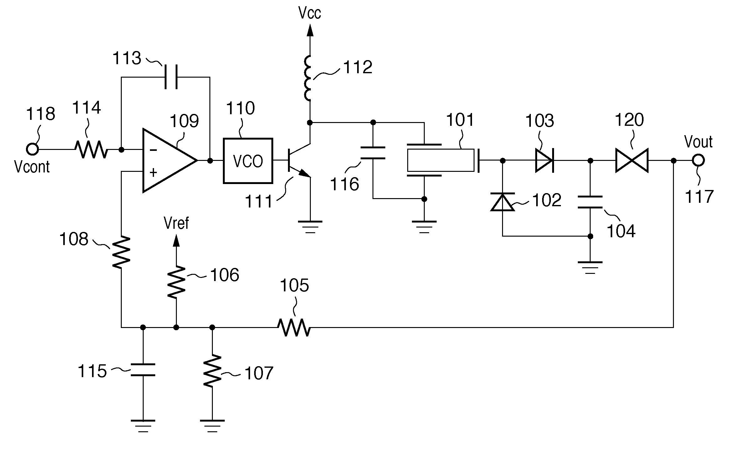
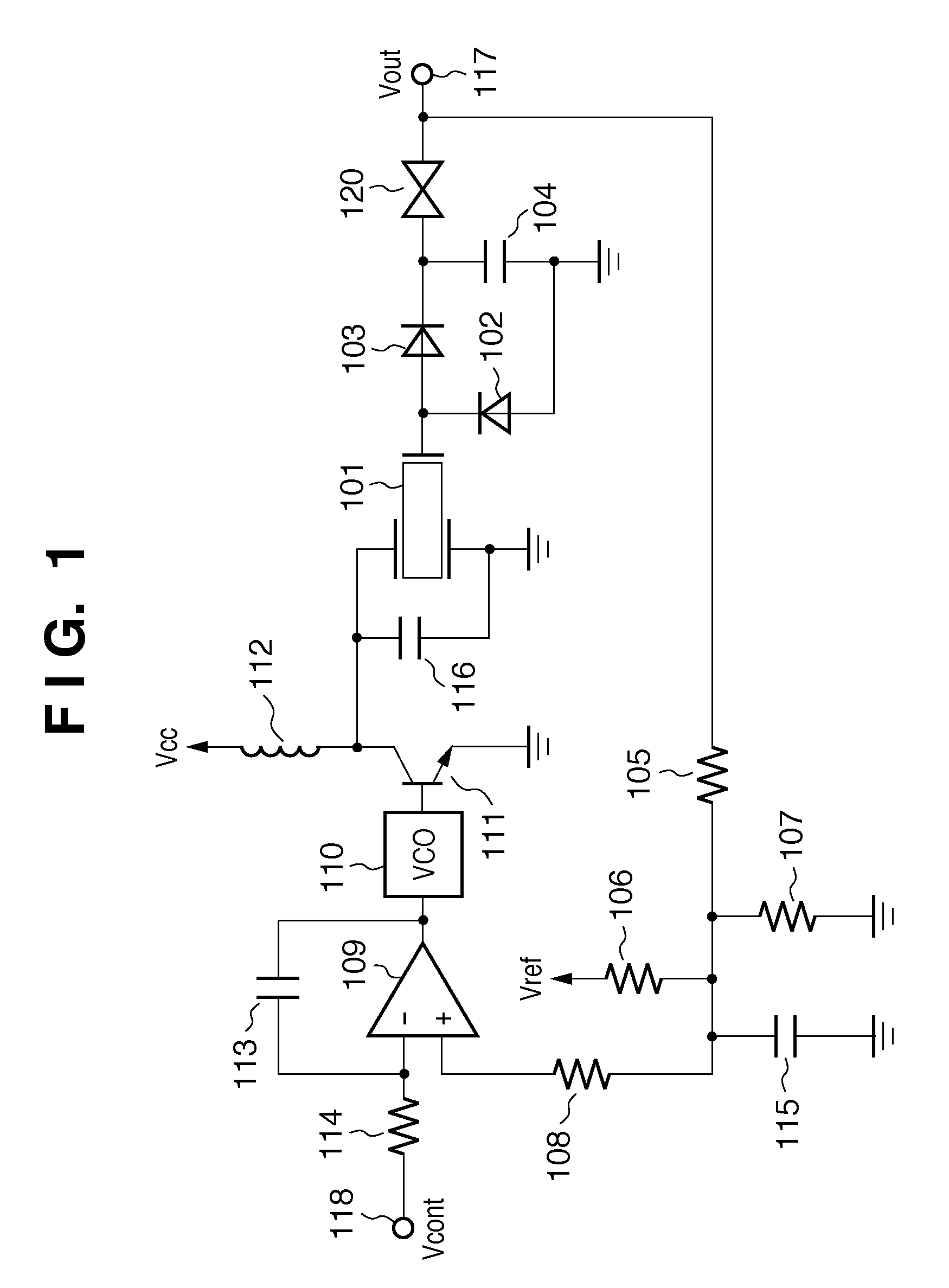
[0059]FIG. 1 is a circuit diagram that shows an example of a piezoelectric transformer type high-voltage power supply apparatus according to Embodiment 1. Note that the description is shortened by giving the same reference numerals to previously described locations. Also, the invention is effective for a high-voltage power supply apparatus that outputs either positive voltage or negative voltage. Here, as one example, a high-voltage power supply apparatus that outputs positive voltage will be described.

[0060]A piezoelectric transformer 101 outputs a highest voltage at a predetermined resonance frequency. A voltage-controlled oscillator 110, a field-effect transistor 111, an inductor 112, and a capacitor 116 are an example of a generating unit that generates a drive frequency (a signal that oscillates at the drive frequency) for driving the piezoelectric transformer 101 throughout a predetermined frequency range that includes the resonance frequency. Ordinarily, frequency refers to t...

embodiment 2

[0103]Below, Embodiment 2 of the invention will be described based on FIGS. 6, 7, and 8. However, a description of matters described in Embodiment 1 will be omitted here.

[0104]FIG. 6 is a circuit diagram of a piezoelectric transformer type high-voltage power supply apparatus according to Embodiment 2. Embodiment 2 mainly differs from Embodiment 1 in that a Zener diode 121 is adopted as a constant-voltage element.

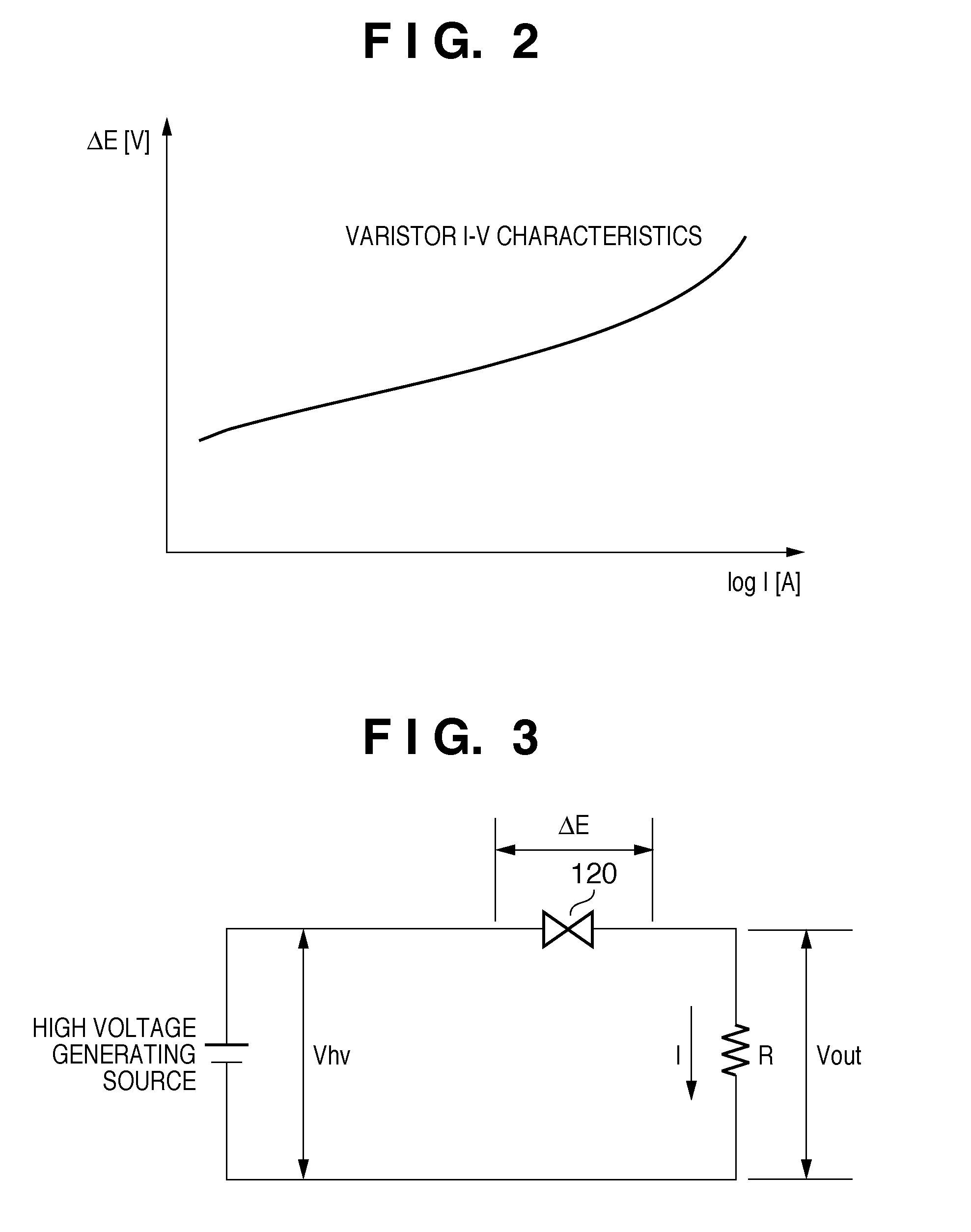
[0105]FIG. 7 shows current-voltage characteristics of an ordinary Zener diode 121. The horizontal axis indicates current I (logarithmic). The vertical axis indicates the both-end voltage of the Zener diode 121. As is understood from a comparison of FIG. 7 and FIG. 2, the voltage characteristics of the Zener diode 121 do not depend on the current that flows to the extent of a varistor. Thus, with respect to the both-end voltage ΔE of the Zener diode 121, the Zener voltage is maintained in a wide current range.

[0106]FIG. 8A shows frequency characteristics for a case where a Ze...

embodiment 3

[0110]Below, Embodiment 3 of the invention will be described based on FIGS. 9, 10, and 11. However, a description of matters described in the previous exemplary embodiments will be omitted here. FIG. 9 is a circuit diagram of a piezoelectric transformer type high-voltage power supply apparatus according to Embodiment 3. Embodiment 3 mainly differs from the previous exemplary embodiments in that a varistor 120 is inserted as a constant-voltage element, and a resistor 122 is further connected in parallel relative to the varistor 120.

[0111]FIG. 10 shows current-voltage characteristics when the varistor 120 and a resistor 122 are connected in parallel. The horizontal axis indicates the current I (logarithmic). The vertical axis indicates the both end voltage of the varistor. As features of this exemplary embodiment, I-V characteristics of the resistor in a region where current is small are dominant, and I-V characteristics of the varistor in a region where current is large are dominant....


PUM


Abstract

The voltage at a spurious frequency is decreased while maintaining as much as possible the voltage at a resonance frequency of a piezoelectric transformer, thus controlling a wide voltage range with a comparatively low cost configuration. A high-voltage power supply apparatus includes a piezoelectric transformer that outputs a highest voltage at a predetermined resonance frequency, and a generating unit that generates a signal that oscillates at a drive frequency that drives the piezoelectric transformer, throughout a frequency range that includes the resonance frequency. Furthermore, the high-voltage power supply apparatus includes an output terminal connected to the piezoelectric transformer, and a constant-voltage element inserted in a path that couples the piezoelectric transformer and the output terminal.

Description

BACKGROUND OF THE INVENTION[0001]1. Field of the Invention[0002]The present invention relates to an image forming apparatus, and more specifically relates to a high-voltage power supply apparatus employed in an image forming apparatus.[0003]2. Description of the Related Art[0004]In an electrophotographic image forming apparatus, transfer of a toner image is expedited by applying a direct current bias voltage to a transfer roller formed by wrapping a roller-like conductive rubber around a metal shaft. In order for transfer to be performed well, ordinarily, electric current of high voltage (voltage of at least several hundred volts greater than the voltage of a commercial power source) and about 10 μA is caused to flow to the transfer roller.[0005]In order to generate this sort of high voltage, conventionally, a wire wound type electromagnetic transformer is used. However, an electromagnetic transformer is an obstacle to reducing the size and weight of a high-voltage power supply appa...

Claims


Application Information

Patent Timeline
IPC IPC(8): G05F1/63
CPCG05F1/63
Inventor NAGASAKI, OSAMUMANO, HIROSHI
Owner CANON KK
Why Eureka
Try Eureka