Method for laying and interlocking panels

a technology of interlocking panels and panels, which is applied in the direction of building repairs, tongue/groove making apparatus, walls, etc., can solve the problems of greater or lesser decrease in inclination, and achieve the effect of reducing inclination, reducing inclination, and reducing inclination

Inactive Publication Date: 2006-06-27
AKZENTA PANEELE PROFILE GMBH
View PDF147 Cites 29 Cited by
  • Summary
  • Abstract
  • Description
  • Claims
  • Application Information

AI Technical Summary

Benefits of technology

[0009]According to the new method, panels to be laid in the second row can be fitted by a single person. A new panel can be interlocked both with panels of a first row and with a previously laid panel of the second row. This does not require interlocking of the short narrow sides of two panels lying in one plane in a manner that expands and deforms the retaining profiles.
[0027]The laying method is particularly suitable if the panels consist essentially of an MDF (medium-density fiberboard), HDF (high-density fiberboard), or particleboard material. These materials are easy to process and can be given a sufficient surface quality by means of cutting processes, for example. In addition, these materials display good dimensional stability of the milled profiles.

Problems solved by technology

Depending on the stiffness of the panels, this can result in more or less strong torsion and thus in a greater or lesser decrease in the inclination.

Method used


Image

  • Method for laying and interlocking panels
  • Method for laying and interlocking panels
  • Method for laying and interlocking panels

Examples


Embodiment Construction

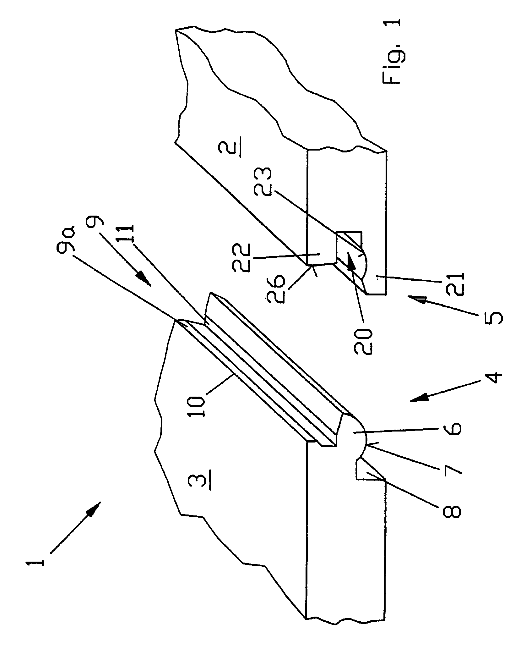
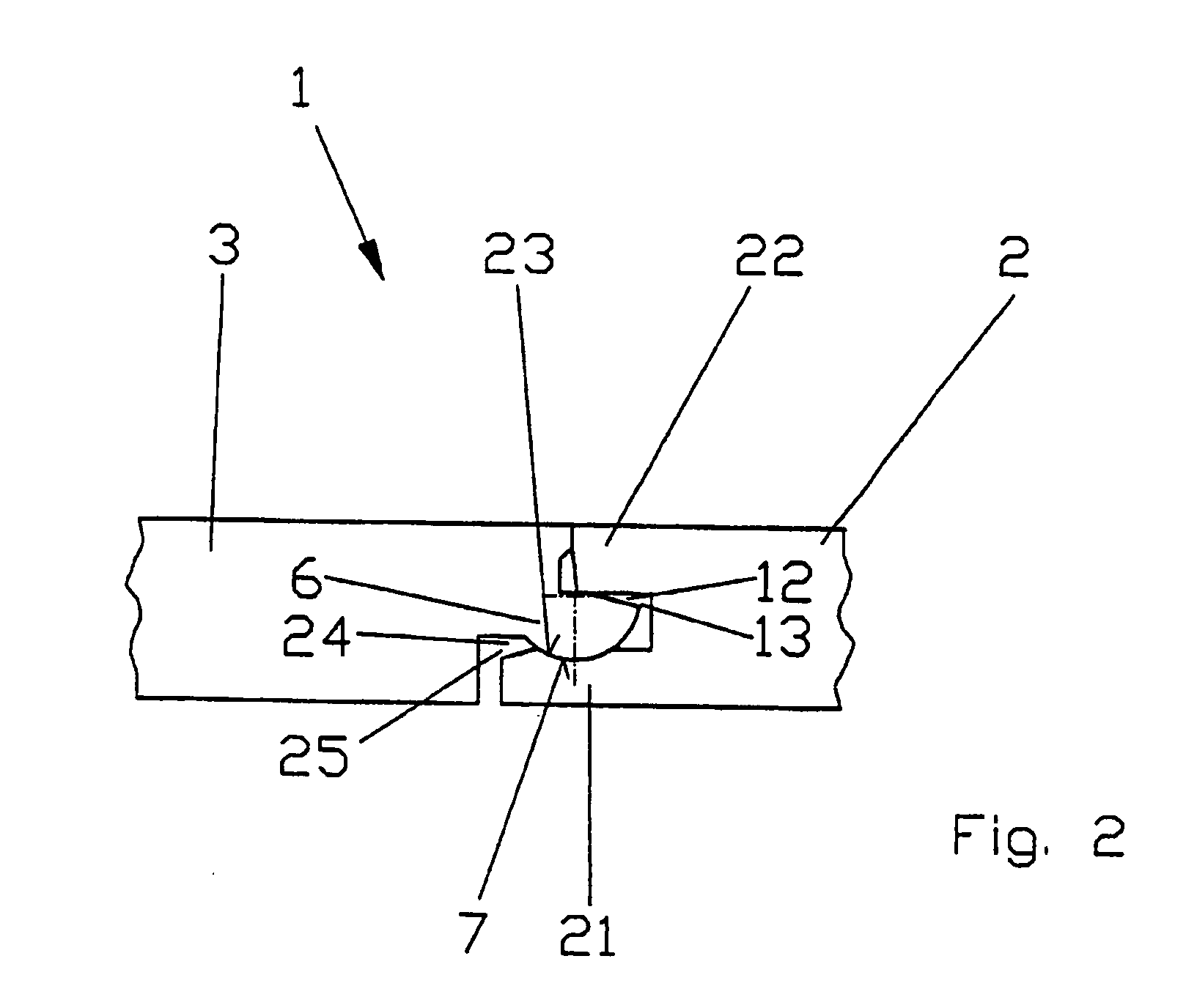
[0039]According to the drawing, fastening system 1, required for the method for laying and interlocking rectangular panels, is explained based on oblong, rectangular panels 2 and 3, a section of which is illustrated in FIG. 1. Fastening system 1 displays retaining profiles, which are located on the narrow sides of the panels and designed as complementary form-fitting profiles 4 and 5. The opposite form-fitting profiles of a panel are of complementary design in each case. In this way, a further panel 3 can be attached to every previously laid panel 2.

[0040]Form-fitting profiles 4 and 5 are based on the prior art according to German utility model G 79 28 703 U1, particularly on the form-fitting profiles of the practical example. The form-fitting profiles according to the invention are developed in such a way that they permit the articulated and resilient connection of panels.

[0041]One of the form-fitting profiles 4 of the present invention is provided with a joint projection 6 protrud...


PUM


Abstract

Rectangular floor panels, a fastening system for joining the panels, and a method for laying and interlocking the panels are disclosed. The panels are provided complementary, form-fitting retaining profiles extending over the length of the sides. The complementary edges of the panels allow two adjacent panels to be positively joined such that displacement of the panels away from one another is prevented, while enabling articulation of the panels with respect to one another at the joint location. The method of installation provides for installing a new panel to a first row and a panel in a second row by first joining the new panel to the panel of the second row at its short side, followed by pivoting the new panel upwards out of the plane of the laid panels along its long side, along with at least the adjacent end of the first panel in the second row, into an inclined position, and sliding the new panel into the retaining profile of the panels in the first row. The new panel and the raised end of the panel in the second row are then pivoted down into the plane of the laid panels. Laying of panels continues according to this process until the complete floor assembly has been laid.

Description

CROSS-REFERENCE TO RELATED APPLICATIONS[0001]This application is a continuation of and co-owned U.S. patent application Ser. No. 09 / 609,251, filed with the U.S. Patent and Trademark Office on Jun. 30, 2000 entitled “Method for Laying and Interlocking Panels”, now U.S. Pat. No. 6,804,926, which is a continuation of PCT / DE00 / 00870, filed Jun. 22, 2000 in Germany by the inventor herein, the specifications of which are incorporated herein by reference.BACKGROUND OF THE INVENTION[0002]1. Field of the Invention[0003]The invention relates to a method for laying and interlocking panels, particularly via a fastening system consisting of positive retaining profiles provided on the narrow sides of the panels, which extend over the length of the narrow sides and are provided with joint projections or complementary joint recesses.[0004]2. Background of the Prior Art[0005]German utility model G 79 28 703 U1 describes a generic method for laying and interlocking floor panels with positive retainin...

Claims


Application Information

Patent Timeline
Patent Type & Authority Patents(United States)
IPC IPC(8): E04F15/02B27F1/04E04F15/04
CPCB27F1/04E04F15/02E04F15/04E04F2201/0107E04F2201/0115Y10T403/65E04F2201/0138E04F2201/0153E04F2201/023E04F2201/07Y10T403/655E04F2201/0123
Inventor RALF, EISERMANN
Owner AKZENTA PANEELE PROFILE GMBH
Why Eureka
Try Eureka