Lawnmower having mulching cutter deck assembly

a mower and cutter technology, applied in the field of mowers, can solve the problems of difficult installation of plates within the cutting chambers of the mower, promote clogging in the chamber, etc., and achieve the effect of mulching grass clippings, preventing any build-up of grass clippings, and reducing the efficiency of the mower

Active Publication Date: 2006-06-27
METALCRAFT OF MAYVILLE +1
View PDF66 Cites 45 Cited by
  • Summary
  • Abstract
  • Description
  • Claims
  • Application Information

AI Technical Summary

Benefits of technology

[0008]The present invention is a mulching system for a lawnmower that operates to effectively mulch grass clippings formed by the mower within a cutting chamber without forming clogs or other obstructions within the mowing chamber, and without reducing the efficiency of the mower. The mulching system includes a plate secured within each cutting chamber of the mower blade. Each plate has a central section that is mounted in the center of the associated cutting chamber and a pair of outer sections that extend outwardly from the central section. The plates are formed to be generally parallel to the cutter blade, and include opposed pairs of flanges on each outer section of the plate. The flanges are angled to direct grass clippings moving within the cutting chamber downwardly through the cutting chamber into contact with the cutting blades for a more effective mulching and dispersion of the clippings. Further, the overall length of each plate is less than the diameter of the cutting chamber, such that the plate does not interfere with the airflow through the high pressure zone formed near the outer circumference of the cutting chamber, thereby preventing any build-up of grass clippings within the cutting chamber.
[0009]In mowers which have more than one cutting chamber, the mulching system of the present invention also preferably additionally includes baffles which help direct airflow and the entrained grass clippings toward the blades for mulching.

Problems solved by technology

However, due to the structure of the deflectors, these plates are difficult to install within the cutting chambers of the decks.
Also, the positioning of the deflectors around the periphery of the cutting chamber tends to promote clogging in the chamber because the deflectors disrupt airflow in the highest pressure region of the cutting chamber.

Method used


Image

  • Lawnmower having mulching cutter deck assembly
  • Lawnmower having mulching cutter deck assembly
  • Lawnmower having mulching cutter deck assembly

Examples


Embodiment Construction

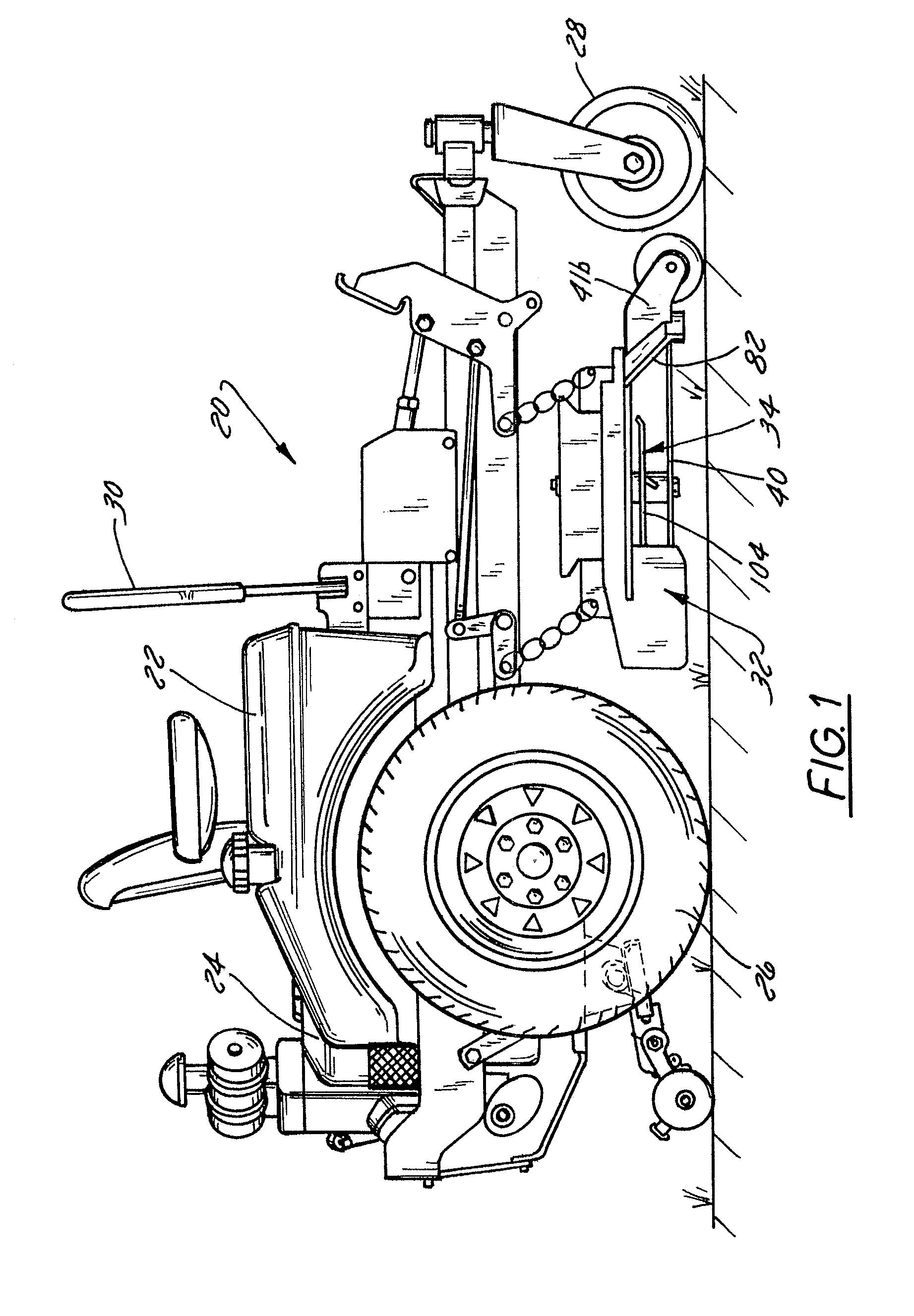
[0021]A zero turn mower with which the mulching system constructed in accordance with the present invention is utilized is illustrated generally at 20 in FIG. 1. The mower 20 includes a frame 22 that supports a motor 24 and that is supported by rear drive wheels 26 and front casters 28. The mower 20 also includes controls 30 which are utilized to control the speed of the mower 20, and the direction of the mower 20. A mower deck 32 is secured to the frame 22 of the mower 20 in a vertically adjustable manner.

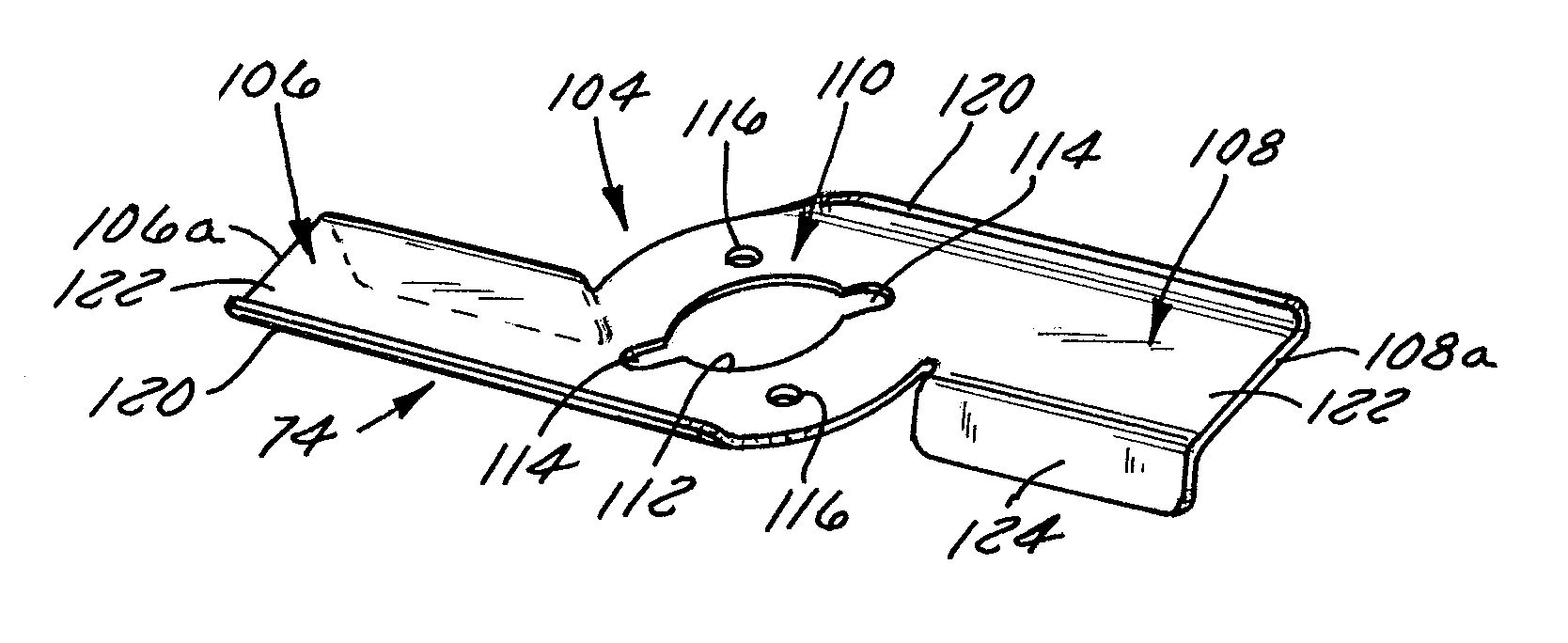
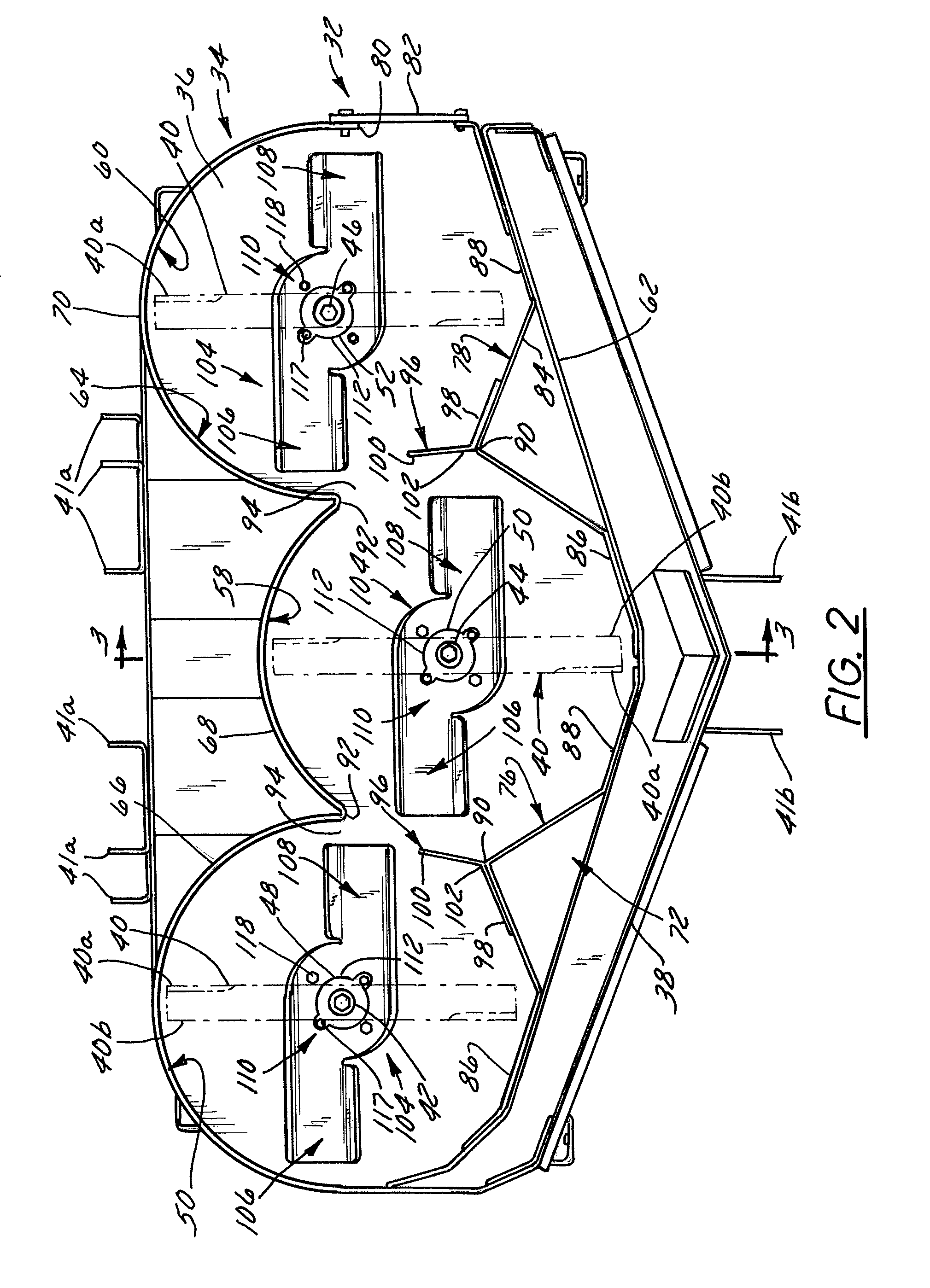
[0022]The cutter deck 32 employs a mulching system 34 constructed in accordance with a preferred embodiment of the invention and is illustrated best in FIGS. 2–4. While the cutter deck 32 of this embodiment is a three-blade deck, it is to be understood that some or all aspects of the invention are applicable to single and multiblade decks of varying widths and having different numbers of blades.

[0023]Referring to FIG. 2, the cutter deck 32 includes a top deck 36 and a skirt 38 whi...


PUM


Abstract

A mulching assembly for a mower deck that has one or more cutting chambers includes a channeling plate in each cutting chamber. The channeling plate is configured to optimize air and clipping flow through the cutting chamber for mulching and dispersal of the clippings without disrupting airflow and consequently creating obstructions in the high-pressure outer region of the cutting chamber. Each channeling plate is spaced from the outer perimeter of the cutting chamber, extends in a generally non-radial direction generally parallel to the bottom surface of the cutter deck, and is mounted to the deck directly above the cutting blade in each cutting chamber.

Description

CROSS REFERENCE TO RELATED APPLICATIONS[0001]This application claims priority from U.S. Provisional Patent Application Ser. No. 60 / 519,491 filed on Nov. 13, 2003, the entire contents of each of which are hereby expressly incorporated by reference into the present application.BACKGROUND OF THE INVENTION[0002]1. Field of the Invention[0003]The invention relates to lawnmowers and, more particularly, relates to a mulching type lawnmower having a mulching system configured to optimize the flow of air and clippings through the cutting chamber(s) of the lawnmower's deck.[0004]2. Discussion of the Related Art[0005]In an attempt to optimize their cutting performance, mulching type lawnmowers often include deflectors or other structures within the deck that are configured to deflect grass clippings downwardly from the top of the deck into the path of the cutting blades for additional cutting. These structures typically comprise triangular deflector plates located at the perimeter of the cutti...

Claims


Application Information

Patent Timeline
Patent Type & Authority Patents(United States)
IPC IPC(8): A01D67/00A01D34/00A01D43/08
CPCA01D43/08A01D34/005
Inventor BOECK, KEVIN A.SUGDEN, DAVID J.WANIE, TODD R.
Owner METALCRAFT OF MAYVILLE
Why Eureka
Try Eureka