
Slide-in structure

a sliding structure and slide technology, applied in the direction of incorrect coupling prevention, coupling device connection, electrical apparatus, etc., can solve the problem that the fastening structure of the connector 104 has very little capacity to buffer shock or vibration, and achieve the effect of increasing flexibility and reducing alignment stress

Active Publication Date: 2006-06-27
HTC CORP
View PDF3 Cites 52 Cited by
  • Summary
  • Abstract
  • Description
  • Claims
  • Application Information

AI Technical Summary

Benefits of technology

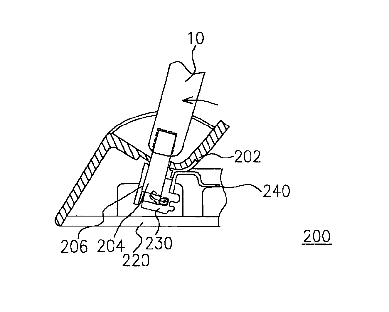
[0009]Accordingly, one object of the present invention is to provide a slide-in structure for a personal digital assistant (PDA) cradle set capable of increasing flexibility and reducing alignment stress when a PDA module is inserted into the cradle set to engage with a connector within the cradle set.
[0010]A second object of this invention is to provide a slide-in structure for a personal digital assistant (PDA) cradle set. The slide-in structure deploys a sliding stand to serve as a fastening structure for the connector in the cradle set so that the connector within the cradle set for engaging with a PDA module is protected against any damages resulting from undesirable external forces.
[0014]In this invention, the slide-in structure buffers the connector in the cradle set against any stress due to misalignment and external vibrating force. Furthermore, the sliding stand of this invention is able to provide positional tolerance for the connector in the cradle set in mating with the connector of the PDA module, in comparison with the conventional fixed connector design.

Problems solved by technology

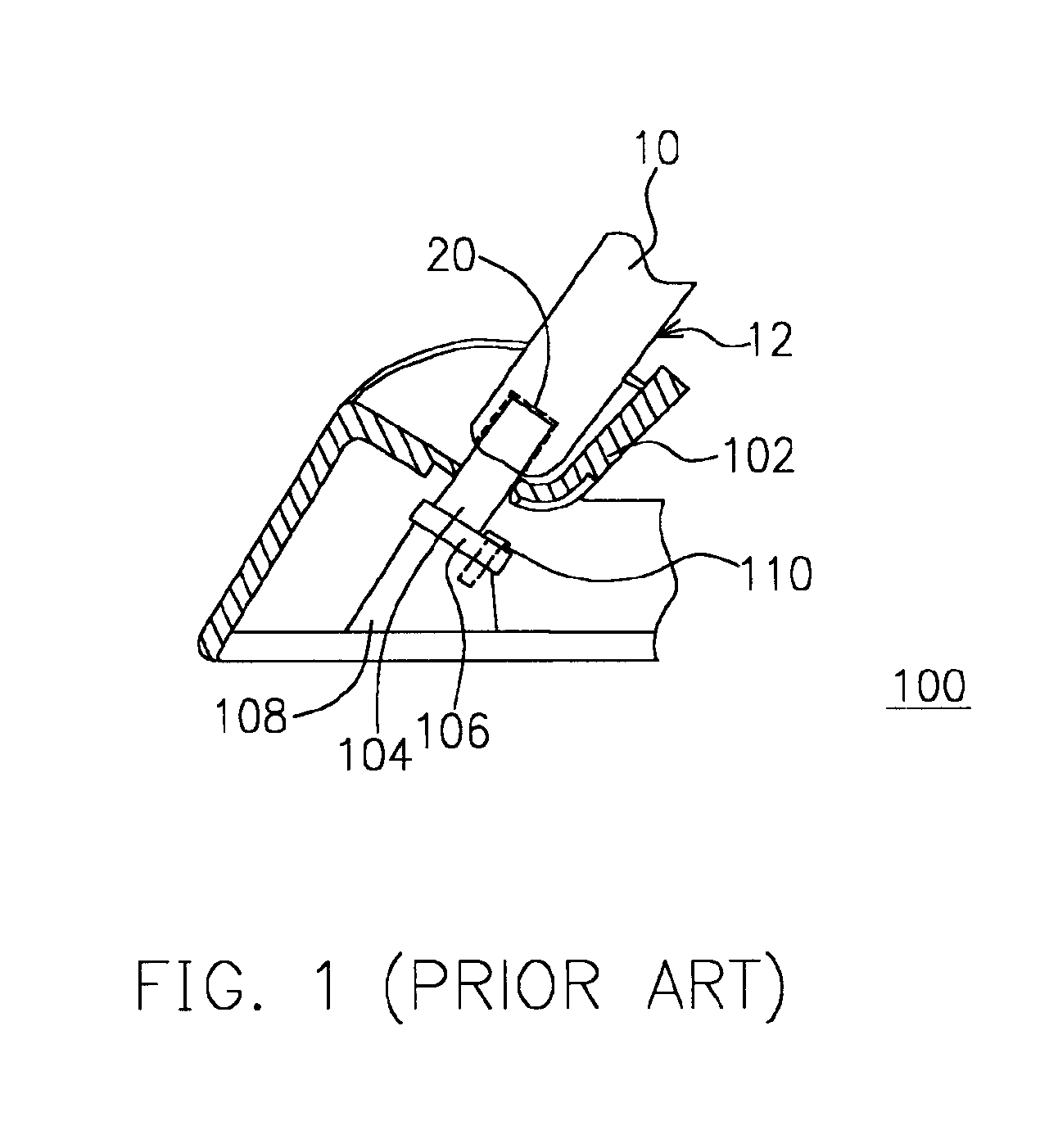
In addition, the fastening structure of the connector 104 also has very little capacity to buffer any shock or vibration.

Method used


Image

  • Slide-in structure
  • Slide-in structure
  • Slide-in structure

Examples


Embodiment Construction

[0021]Reference will now be made in detail to the present preferred embodiments of the invention, examples of which are illustrated in the accompanying drawings. Wherever possible, the same reference numbers are used in the drawings and the description to refer to the same or like parts.

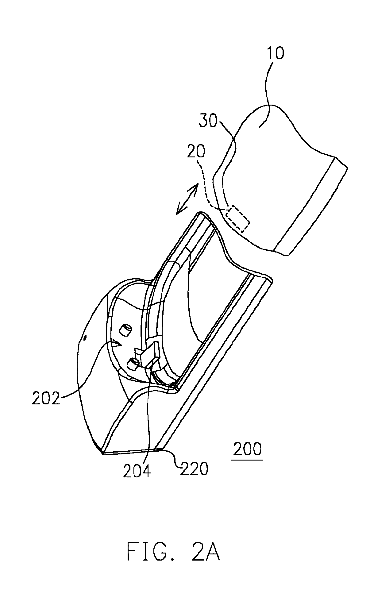
[0022]As shown in FIG. 2A, a PDA module 10 has a connector terminal 30. The connector terminal 30 is located at a bottom end of the PDA module 10, for example. The connector terminal 30 is the end that has a built-in connector 20 (a female connector) for engaging with another connector 204 (a male connector) in a cradle set 200. In this embodiment, the PDA module 10 is used in the illustration. However, the application of this invention is not limited to the PDA module. For example, other devices such as PDA type mobile phones, smart phones or portable electronic devices having a function similar to the PDA module may also deploy the slide-in structure described in this invention.

[0023]A slide-in str...


PUM


Abstract

A slide-in structure (210) inside a cradle set (200) for accommodating a personal digital assistant (PDA) module (10) is disclosed. The slide-in structure comprises a base plate (220), a sliding stand (230) and a pushing arm (240). A connector (204) of the cradle set is fastened to the sliding stand via a circuit board (206). The base plate has a pair of sidewalls (222, 224) and two sliding grooves (226) located on of the sidewalls. The two ends of the sliding stand are inserted into the respective sliding grooves so that the sliding stand is free to move relative to the sliding grooves. The pushing arm is in contact with the sliding stand. The pushing arm resiliently pushes the sliding stand to one side of the sliding grooves and provides a buffering force when the PDA module engages with / disengages from the connector in the cradle set.

Description

CROSS REFERENCE TO RELATED APPLICATIONS[0001]This application claims the priority benefit of Taiwan application serial no. 92208777, filed May 14, 2003.BACKGROUND OF INVENTION[0002]1. Field of the Invention[0003]The present invention generally relates to a slide-in structure, and more particularly, the present invention relates to a slide-in structure having a buffered self-alignment connector used in a cradle set for a handheld electronic device.[0004]2. Description of the Related Art[0005]Personal digital assistant (PDA) is one of the most common portable entertainment tools to be carried around in our daily life. At first, the PDA was designed as a general-purpose electronic notebook for managing traveling schedules, recording events and logging communication. However, as computational speed of computers continues to increase, and networking and wireless communication continues to advance, the PDA is used for communication, network surfing, playing games or serving as a multimedi...

Claims


Application Information

Patent Timeline
IPC IPC(8): H01R13/64H01R13/629
CPCH01R13/62905Y10S439/929H01R2201/16
Inventor HSU, HSI-HSINGCHU, CHU-YANGHUANG, CHIEN-LUNGWANG, WILLIAMHUNG, LEADER
Owner HTC CORP
Learn More