Penile prosthesis and surgical instruments for implantation of penile prostheses

a penile prosthesis and surgical instrument technology, applied in the field of penile erection devices and penile prosthesis implantation instruments, can solve the problems of presenting difficulties with respect to the placement of the proximal tip without current instruments, which are not entirely satisfactory, and are encountered in the ar

Inactive Publication Date: 2006-06-27
BOSTON SCI SCIMED INC
View PDF22 Cites 67 Cited by
  • Summary
  • Abstract
  • Description
  • Claims
  • Application Information

AI Technical Summary

Benefits of technology

The technical effect of this patent is that it provides a special tool designed to close wounds after implanting a penile prosthesis during sexual reconstructive surgeries. This tool has been developed to prevent accidental damages caused by a suturing needle while also providing better protection against bacterial contamination.

Problems solved by technology

The technical problem addressed in this patent text is the difficulty and safety concerns associated with currently available tools used for implanting penile prostate replacement devices. Current methods require the use of needles and may result in damage to the patient's body. Additionally, there is a lack of effective tools for accurately measuring and closing the incision required for inserting the device. Therefore, there is a need for safer、 easier to use and versatile tools to improve the process of implanting penile prostheses.

Method used


Image

  • Penile prosthesis and surgical instruments for implantation of penile prostheses
  • Penile prosthesis and surgical instruments for implantation of penile prostheses
  • Penile prosthesis and surgical instruments for implantation of penile prostheses

Examples


Embodiment Construction

[0053]As used in the present application the term proximal is meant to convey the part of the body that is situated next to or near the point of attachment or origin or a central point: as located toward the center of the body. As used in the present application the term distal is meant to convey the part of the body that is situated away from the point of attachment or origin or a central point: as located away from the center of the body

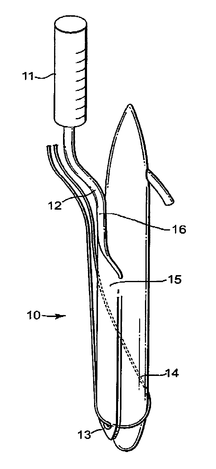
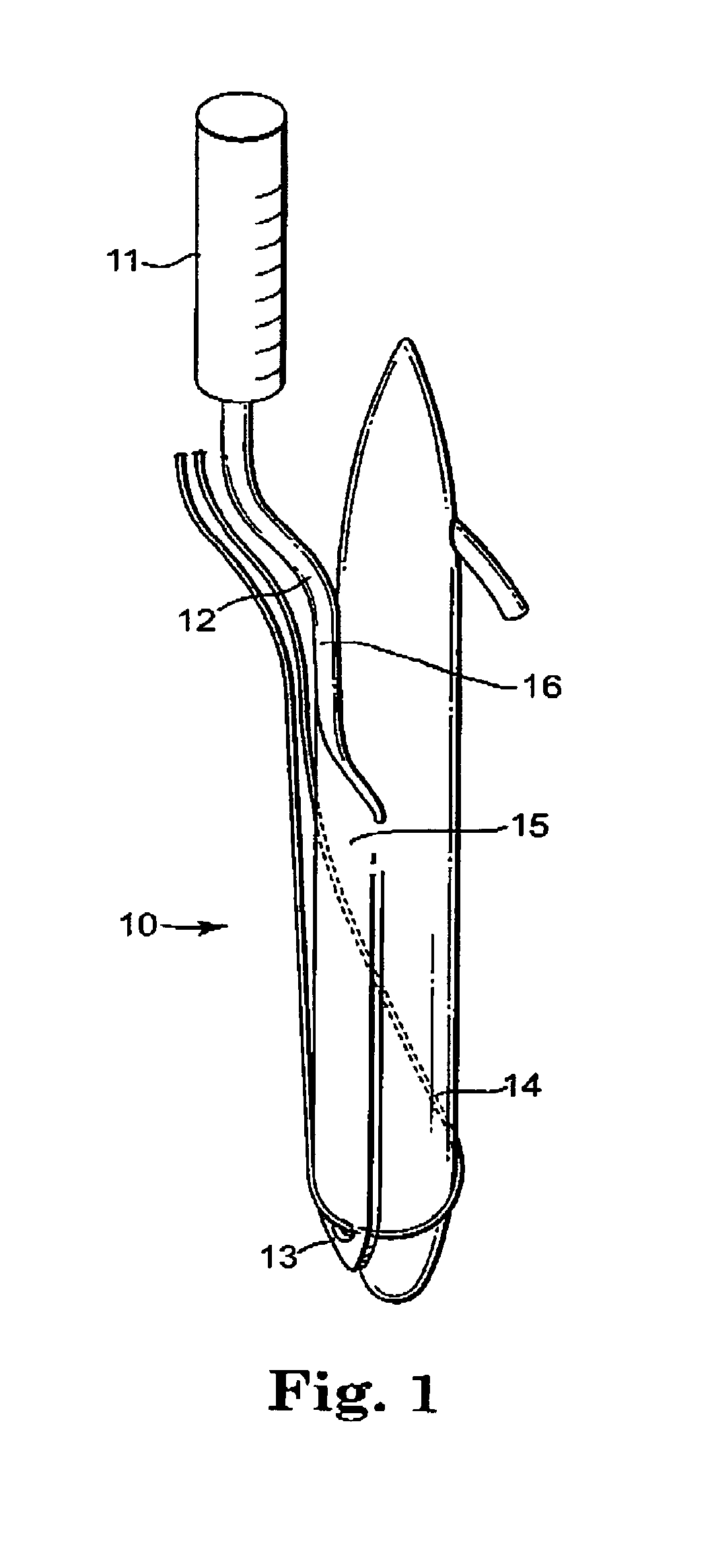
Distal Tip Insertion Tool

[0054]Referring to FIG. 1, the insertion tool 10 in one embodiment of the invention has an elongate shaft and includes a substantially round handle portion 11, a thinner portion 12, and a distal tip portion 13. Intermediate the thinner portion 12 and the distal tip portion 13, the insertion tool 10 includes outwardly angled shaft section 15, and linear handle section 16 that is aligned in space and parallel relation to the axis of the shaft. The distal tip portion 13 preferably includes an opening for receiving a suture 14,...


PUM


Abstract

The invention relates to an improved penile erection device and improved method for implanting such devices into the corpus cavernosum of the penis. The invention further relates to tools for implanting the improved penile erection device. Furthermore, the invention relates to insertion tools that permit precise placement of conventional inflatable prostheses cylinders such that puncture or damage of the glans penis does not occur during placement.

Description


Claims


Application Information

Patent Timeline
Owner BOSTON SCI SCIMED INC
Why Eureka
Try Eureka