System for measurement of metallic debris in fluid

a technology for fluid measurement and metallic debris, applied in the direction of magnetic measurement, instruments, measurement devices, etc., can solve the problems of intrusion and/or high cos

Inactive Publication Date: 2006-06-27
THE UNITED STATES OF AMERICA AS REPRESENTED BY THE SECRETARY OF THE NAVY
View PDF4 Cites 10 Cited by
  • Summary
  • Abstract
  • Description
  • Claims
  • Application Information

AI Technical Summary

Problems solved by technology

Currently measurement of machinery wear by detection of wear debris involves removal of oil samples from the machinery for analysis by u

Method used


Image

  • System for measurement of metallic debris in fluid
  • System for measurement of metallic debris in fluid
  • System for measurement of metallic debris in fluid

Examples


Embodiment Construction

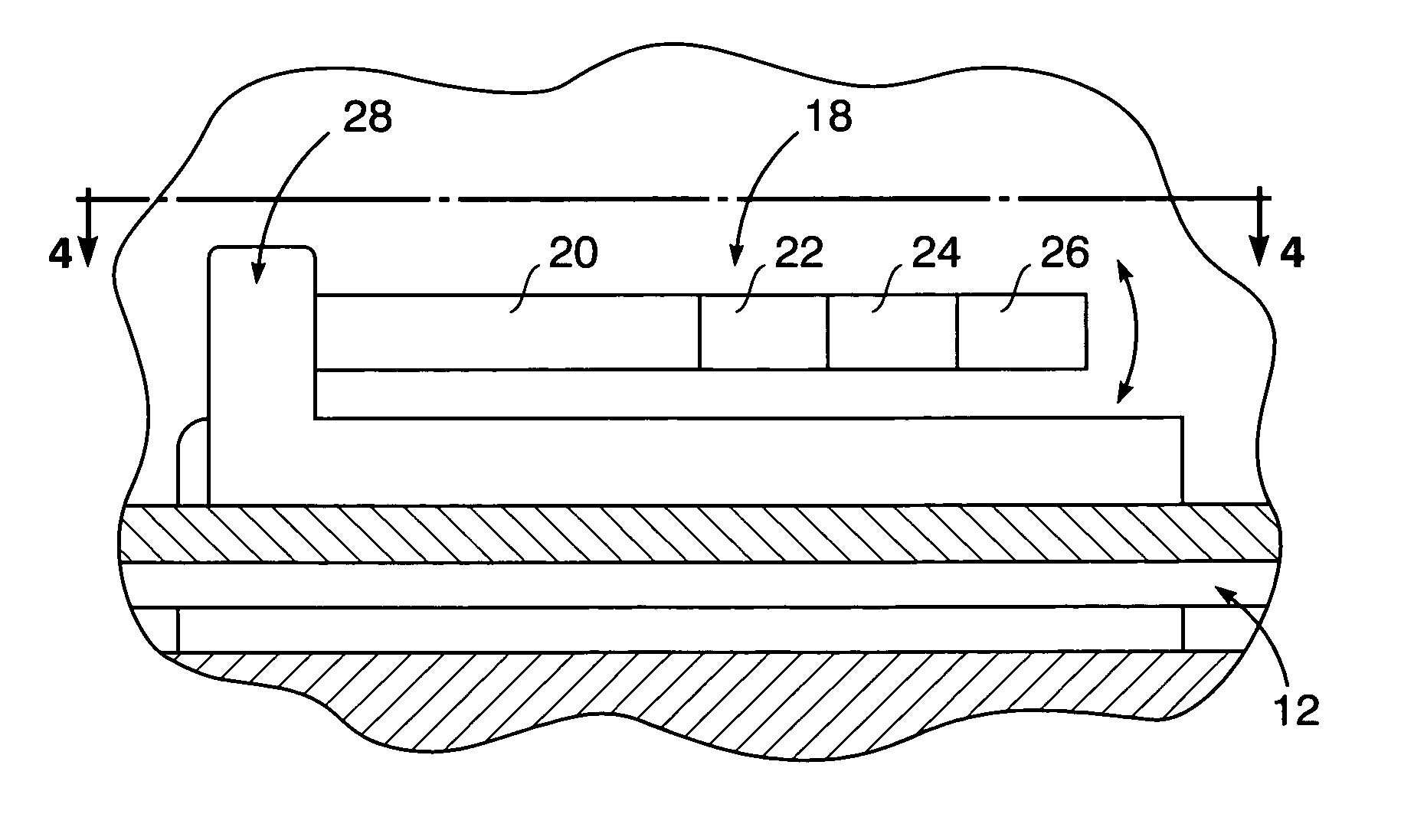
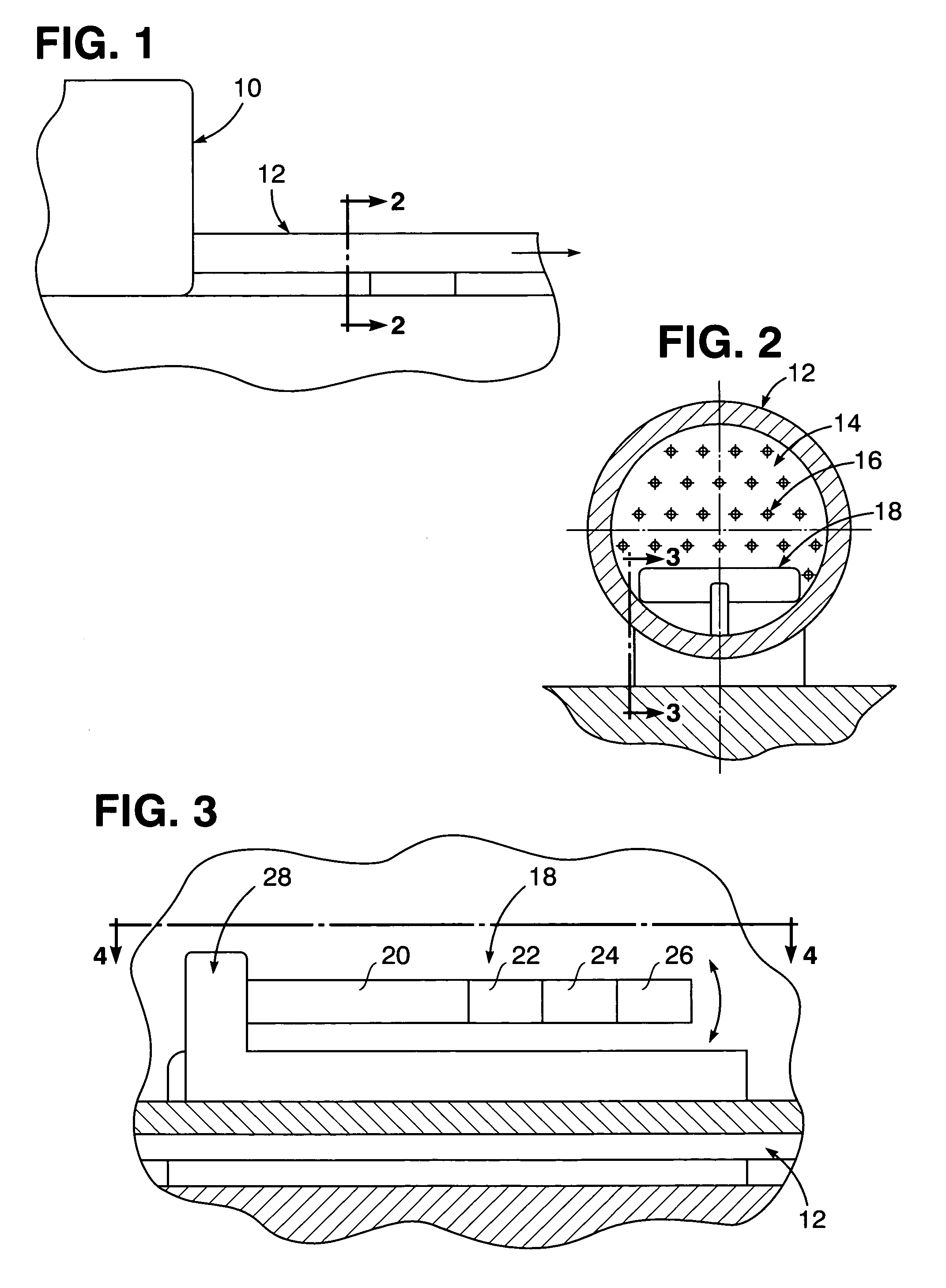
[0012]Referring now to the drawing in detail, pursuant to one embodiment of the present invention wear of machinery 10 for example is monitored by detection of debris within fluid enclosure such as a pipe 12 as shown in FIG. 1. Fluid 14 as shown in FIG. 2, such as non-turbulent water or lubricating oil, is to be tested for the presence of metallic debris therein, such as suspended non-magnetic particles 16 imparting a relatively low viscosity to the fluid 14 so as to enable detection of the debris particles 16 by a micro-mechanical type of sensor arrangement 18.

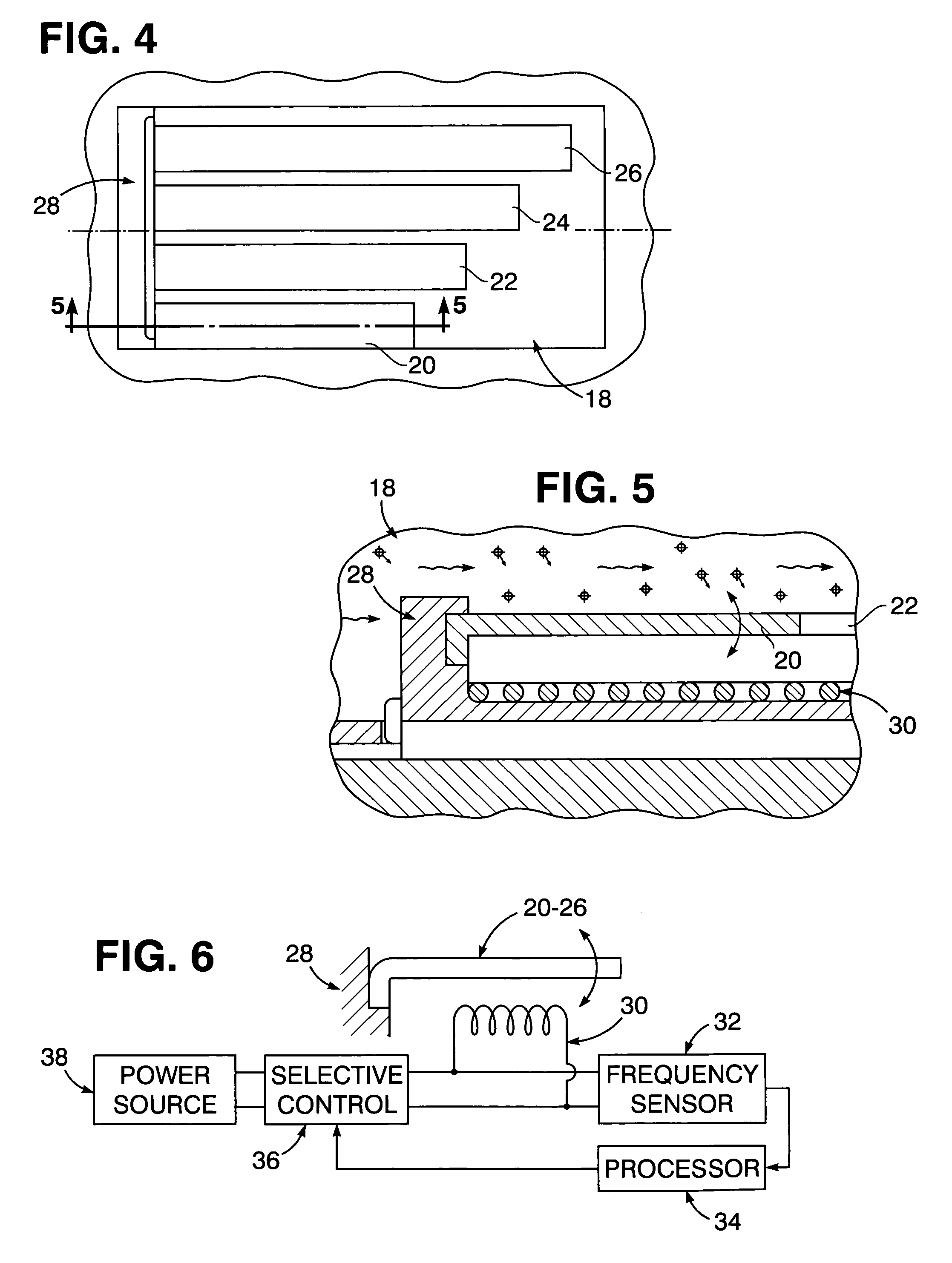
[0013]Referring now to FIGS. 2–5, the debris sensor arrangement 18 embodies a plurality of vibratory cantilever beams 20, 22, 24 and 26 of different lengths anchored at one end thereof within the pipe 12 by a support 28 in overlying relation to electromagnetic coils 30. The cantilever beams 20, 22, 24 and 26 undergo vibratory motion when rendered magnetic within an electromagnetic field generated by the underlying electromagn...


PUM


Abstract

A debris sensor arrangement is positioned within an enclosed body of fluid for detecting the presence of metallic debris particles therein. Debris detection involves exposure of cantilever beams to the fluid when magnetized within an electromagnetic field to attract the metallic debris particles thereon and induce vibratory motion thereof at a resonant frequency varied by changes in the density of the debris particles magnetically held thereon. Measurement of the resonance frequency reflecting the density of the debris particles within the fluid being tested thereby monitors the corresponding wear of machinery reflected by the debris density.

Description

STATEMENT OF GOVERNMENT INTEREST[0001]The invention described herein may be manufactured and used by or for the Government of the United States of America for governmental purposes without the payment of any royalties thereon or therefore.[0002]The present invention relates generally to debris detection and measurement in indicate associated mechanical parameters such as machinery wear.BACKGROUND OF THE INVENTION[0003]Currently measurement of machinery wear by detection of wear debris involves removal of oil samples from the machinery for analysis by use of magnetic Hall effect sensors, which may be intrusive and. / or very expensive, where fiber optics types of such sensors are utilized. Other generally known optical fiber systems for monitoring metallic debris require algorithms to discern the metallic debris from air bubbles and other anomalies. It is an important object of the present invention to provide a relatively smaller and less intrusive system for the detection and measure...

Claims


Application Information

Patent Timeline
IPC IPC(8): G01N27/74
CPCG01N33/2858G01N27/74
Inventor MASTRO, STEPHEN A.OVERBY, JOHN K.
Owner THE UNITED STATES OF AMERICA AS REPRESENTED BY THE SECRETARY OF THE NAVY
Why Eureka
Try Eureka