Optical device

a technology of optical devices and optical polarizers, applied in the direction of mountings, polarising elements, instruments, etc., can solve the problems of uneven display or other problems, and the shift in the center reflection wavelength is disadvantageous

Inactive Publication Date: 2006-06-27
DAI NIPPON PRINTING CO LTD
View PDF6 Cites 6 Cited by
  • Summary
  • Abstract
  • Description
  • Claims
  • Application Information

AI Technical Summary

Benefits of technology

[0009]In a preferred embodiment of the present invention, the polymerizable liquid crystal material contains a photopolymerization initiator. This is because, when the polymerizable liquid crystal material is cured, for example, by ultraviolet light, the incorporation of a photopolymerization initiator is preferred from the viewpoint of accelerating polymerization. Further, an optical function layer formed by curing a polymerizable liquid crystal material containing a photopolymerization initiator can effectively develop the advantage of the present invention.
[0010]More preferably, the support is a supporting substrate having an aligning ability. This is advantageous from the viewpoint of the process, because, when an optical function layer can be formed on a supporting substrate having an aligning ability and as such can be used, there is no need to perform the step of transfer and the like.
[0011]According to another aspect of the present invention, there is provided a retardation layer laminate characterized by comprising a support and a retardation layer provided on the support and formed by curing a polymerizable liquid crystal material while retaining nematic regularity, smectic regularity, or cholesteric regularity, said retardation layer laminate having been heat treated at a predetermined temperature, said retardation layer having a percentage reduction in retardation, defined by (Ra-Rb) / Ra, of not more than 5% wherein Ra represents the retardation value of the retardation layer after the heat treatment and Rb represents the retardation value of the retardation layer after reheating the retardation layer laminate at said heat treatment temperature for 60 min. When the retardation layer laminate is incorporated in various image display devices, a change in retardation value upon heating within the above range poses no problem associated with the use of the retardation layer laminate.
[0012]In a preferred embodiment of the present invention, the polymerizable liquid crystal material comprises a photopolymerization initiator and a polymerizable liquid crystal monomer. More preferably, the polymerizable liquid crystal material having cholesteric regularity comprises a photopolymerization initiator, a polymerizable liquid crystal monomer, and a polymerizable chiral dopant. The retardation value is a value associated with the thickness of the retardation layer. The change in thickness of the retardation layer upon heating is estimated to depend upon the amount of the residue of the photopolymerization initiator. Therefore, when the polymerizable liquid crystal material contains a photopolymerization initiator, it is considered that the advantage of the present invention can be utilized.
[0013]More preferably, the support is a supporting substrate having an aligning ability. This is advantageous from the viewpoint of the process, because, when a retardation layer can be formed on a supporting substrate having an aligning ability and as such can be used as a retardation layer laminate, there is no need to perform the step of transfer and the like.
[0014]According to still another aspect of the present invention, there is provided a circularly polarized light controlling optical device characterized by comprising a support and a cholesteric layer provided on the support and formed by curing a polymerizable liquid crystal material while retaining cholesteric regularity, said circularly polarized light controlling optical device having been heat treated at a predetermined temperature, said cholesteric layer having a percentage change in center reflection wavelength, defined by |λa−λb| / λa, of not more than 5% wherein λa represents the center reflection wavelength of the cholesteric layer after the heat treatment and λb represents the center reflection wavelength of the cholesteric layer after reheating the circularly polarized light controlling optical device at said heat treatment temperature for 60 min. For example, when the circularly polarized light controlling optical device is incorporated in an image display device such as a color filter, a change in center reflection wavelength upon heating within the above range poses no problem associated with the use of the circularly polarized light controlling optical device.

Problems solved by technology

Further, when the image display device using the optical device is used as a display in the inside of a car, the image display device is exposed to sunlight and consequently is sometimes heated by the sunlight to 100° C. or above.
The optical device produced by polymerizing the polymerizable liquid crystal material, however, suffers from a problem that, for example, in the case of a cholesteric layer having cholesteric regularity, upon heating, a shift in center reflection wavelength disadvantageously occurs.
Therefore, as described above, in use, when the optical device is incorporated in an image display device such as a liquid crystal display device, disadvantageously, the optical device can be used only in a site not exposed to heat during the production of the image display device.
Further, the stretched phase difference film disadvantageously undergoes a change in phase difference level at 80° C. or above, particularly at 100° C. or above, and, thus, when used, for example, in on-vehicle LCDs, poses an uneven display or other problems.

Method used


Image

  • Optical device
  • Optical device
  • Optical device

Examples


first embodiment

(1) First Embodiment

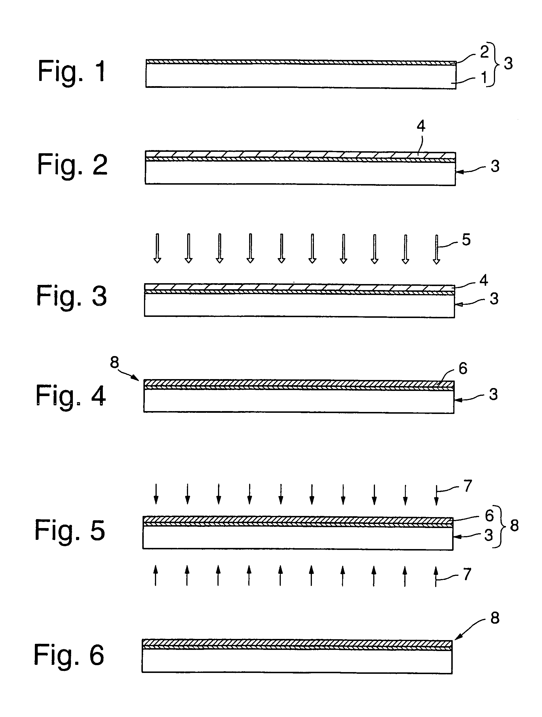
[0048]In the first embodiment, a substrate per se has an aligning ability and constitutes the supporting substrate. Specifically, a stretched film may be mentioned as the supporting substrate in the first embodiment. When the stretched film is used, molecules of the liquid crystal material can be aligned along the direction of stretch. In this embodiment, what is required for providing a supporting substrate is only to provide a stretched film. Therefore, advantageously, this can highly simplify the step of providing a supporting substrate. The stretched film may be commercially available one. If necessary, stretched films of various materials may be formed.

[0049]Specific examples of films for stretched films include: films of polycarbonate-based polymeric materials, polyester-based polymeric materials such as polyallylate and polyethylene terephthalate, polyimide-based polymeric materials, polysulfone-based polymeric materials, polyether sulfone-based polymeric ...

second embodiment

(2) Second Embodiment

[0053]In the second embodiment, the supporting substrate having an aligning ability comprises a transparent substrate and an aligning film provided on the transparent substrate.

[0054]The second embodiment is advantageous in that the direction of aligning can be selected from a relatively wide aligning direction range by selecting the aligning film. Further, various aligning directions can be realized by selecting the type of a coating liquid, for aligning film formation, to be coated onto the transparent substrate, and more effective aligning can be realized.

[0055]Aligning films commonly used, for example, in liquid crystal displays can be suitably used as the aligning film in this embodiment. In general, a polyimide-based or polyvinyl alcohol-based aligning film subjected to rubbing treatment is suitable. Photoaligning films may also be used.

[0056]The transparent substrate used in this embodiment is not particularly limited so far as the substrate is formed of ...

example 1

1% Change to Shorter Wavelength Side

Comparative Example 1

6% Change to Shorter Wavelength Side

[0163]The sample of Example 2 and the sample of Comparative Example 2 were measured for selective reflection center wavelength, were then heated at 100° C. for 60 min, and were again measured for selective reflection center wavelength. The percentage change in center wavelength was determined as described above. The results were as follows.


PUM

PropertyMeasurementUnit
temperatureaaaaaaaaaa

Abstract

An optical device in which a polymerizable liquid crystal material various optical characteristics of which is stable even against heating during manufacture of an optical apparatus such as an image display is cured. The optical device has a support and an optical functional layer made of a cured polymerizable liquid crystal material having a predetermined liquid crystal regularity and provided on the support. The optical device is characterized in that the optical device is subjected to a heat treatment at a predetermined temperature and in that the thickness decrease of the optical functional layer defined by (A-B) / A is 5% or less where A is the thickness of the optical functional layer after the heat treatment, and B is the thickness of the optical functional layer after the optical device is heated for 60 minutes at the heat-treatment temperature.

Description

TECHNICAL FIELD[0001]The present invention relates to a heat-resistant optical device which, even when heat is applied, is stable in various properties.BACKGROUND ART[0002]Optical devices, such as phase difference films and circularly polarized light controlling optical devices, are used, for example, in image display devices. In use, the optical device is in some cases incorporated in image display devices such as liquid crystal display devices. In the production of these image display devices, the assembly is sometimes heated at 200° C. or above, for example, for the formation of a polyimide film used as an aligning film or for the formation of an ITO film as a transparent electrode. Further, when the image display device using the optical device is used as a display in the inside of a car, the image display device is exposed to sunlight and consequently is sometimes heated by the sunlight to 100° C. or above. Therefore, the optical device, such as the phase difference film, used ...

Claims


Application Information

Patent Timeline
Patent Type & Authority Patents(United States)
IPC IPC(8): G02F1/1335C08F2/48G02B5/30G02B7/00
CPCG02B1/10G02B7/008G02B5/3016G02F1/13363
Inventor KASHIMA, KEIJI
Owner DAI NIPPON PRINTING CO LTD
Why Eureka
Try Eureka