Lens system and method for power adjustment

a technology of power adjustment and lens system, applied in the field of lenses, can solve the problems of large iol patient error, and inability to predict refractive error,

Inactive Publication Date: 2006-06-27
ALCON INC
View PDF9 Cites 199 Cited by
  • Summary
  • Abstract
  • Description
  • Claims
  • Application Information

AI Technical Summary

Benefits of technology

[0015]It is also an object of this invention to provide apparatus and methods that enable localized in-situ modification of the surface of a lens to not only restore loss of sight due to cataracts, but which actually improve visual acuity.
[0020]The deformable cells generally are adapted to be moved controllably between a retracted position and an axially-extended position to engage and controllably deform the anterior and / or posterior lens element upon the application of energy from an external energy source, such as a laser source. The number of cells may vary from as few as one to more than 250, and preferably are individually controllable using an external power source. The lens of the invention thus allows for a post-implant power adjustment of an IOL with an inexpensive low power laser source.
[0023]In accordance with another aspect of this invention, the external source that targets and addresses the flow control mechanisms within the IOL may be under the control of a wavefront sensor system, thus allowing for intraoperative lens power calculations while adjusting the lens power.

Problems solved by technology

Since the lens can no longer accommodate, the patient typically needs glasses for reading.
However, in a significant number of cases, after the patient's eye has healed from the cataract surgery, there is a refractive error that could not be predicted.
It is quite common for residual errors after IOL implantation to occur, and in fact, such errors may occur in the vast majority of IOL patients.
Thus, many patients experience an error of over 1.0 diopter.
Although previously known workers in the field of in-situ adjustable lenses have made some progress, the relative complexity of the methods and apparatus developed to date have prevented widespread commercialization of such devices.
However, such gross modifications to lens position or curvature are limited by materials and space constraints.

Method used


Image

  • Lens system and method for power adjustment
  • Lens system and method for power adjustment
  • Lens system and method for power adjustment

Examples


Embodiment Construction

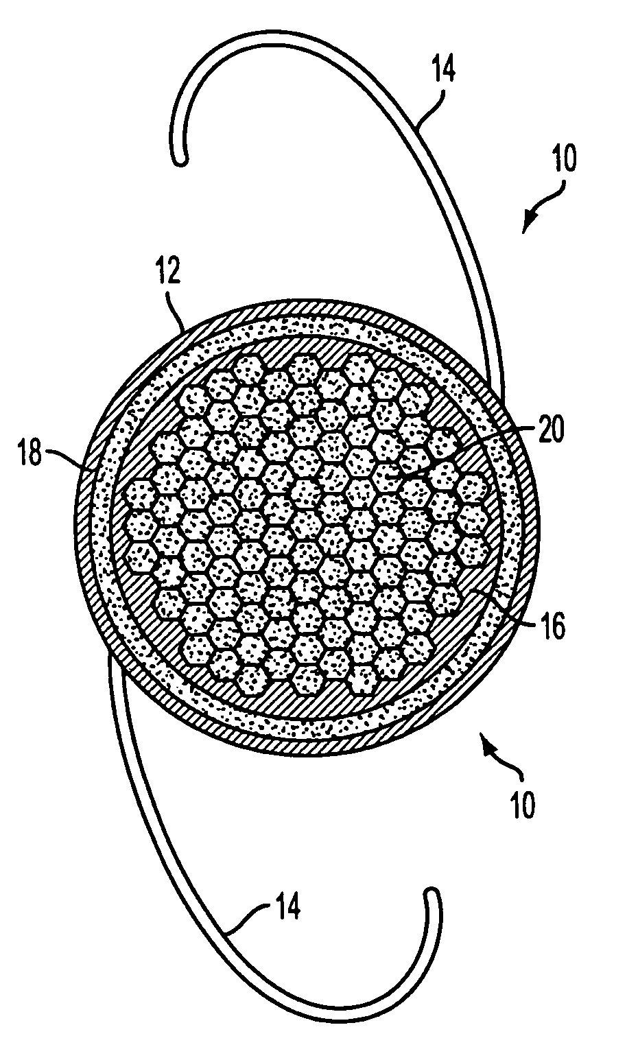
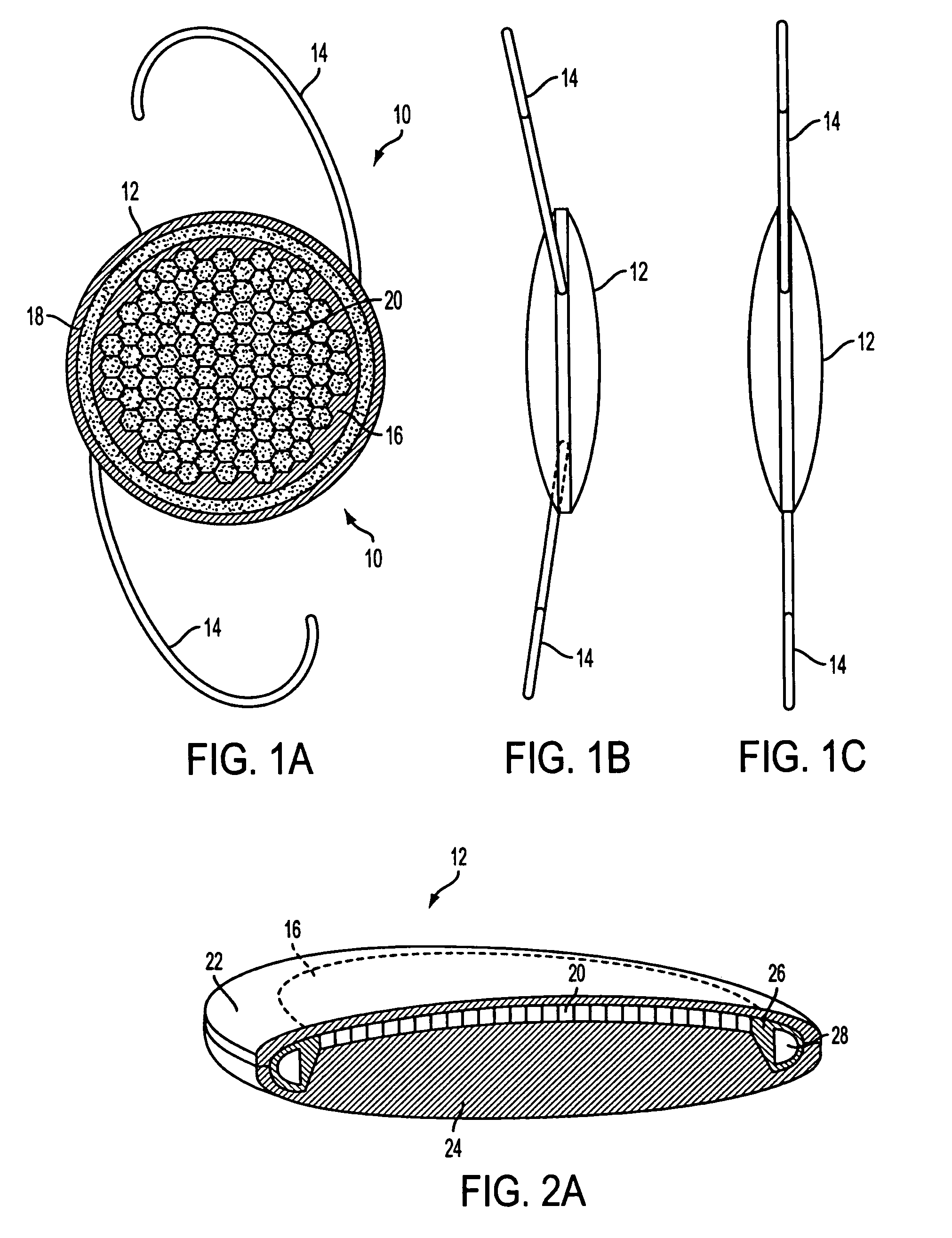
[0037]The present invention is directed to an in-situ adjustable lens system, with particular applicability in the fields of implantable intraocular lenses (“IOLs”) and custom contact lenses. As will be described below, the system of the invention also may be utilized to adjust the power of other types of lenses used for vision correction, for example phakic IOLs and contact lenses. For convenience, the system is first described in the context of exemplary in-the-capsule IOLs.

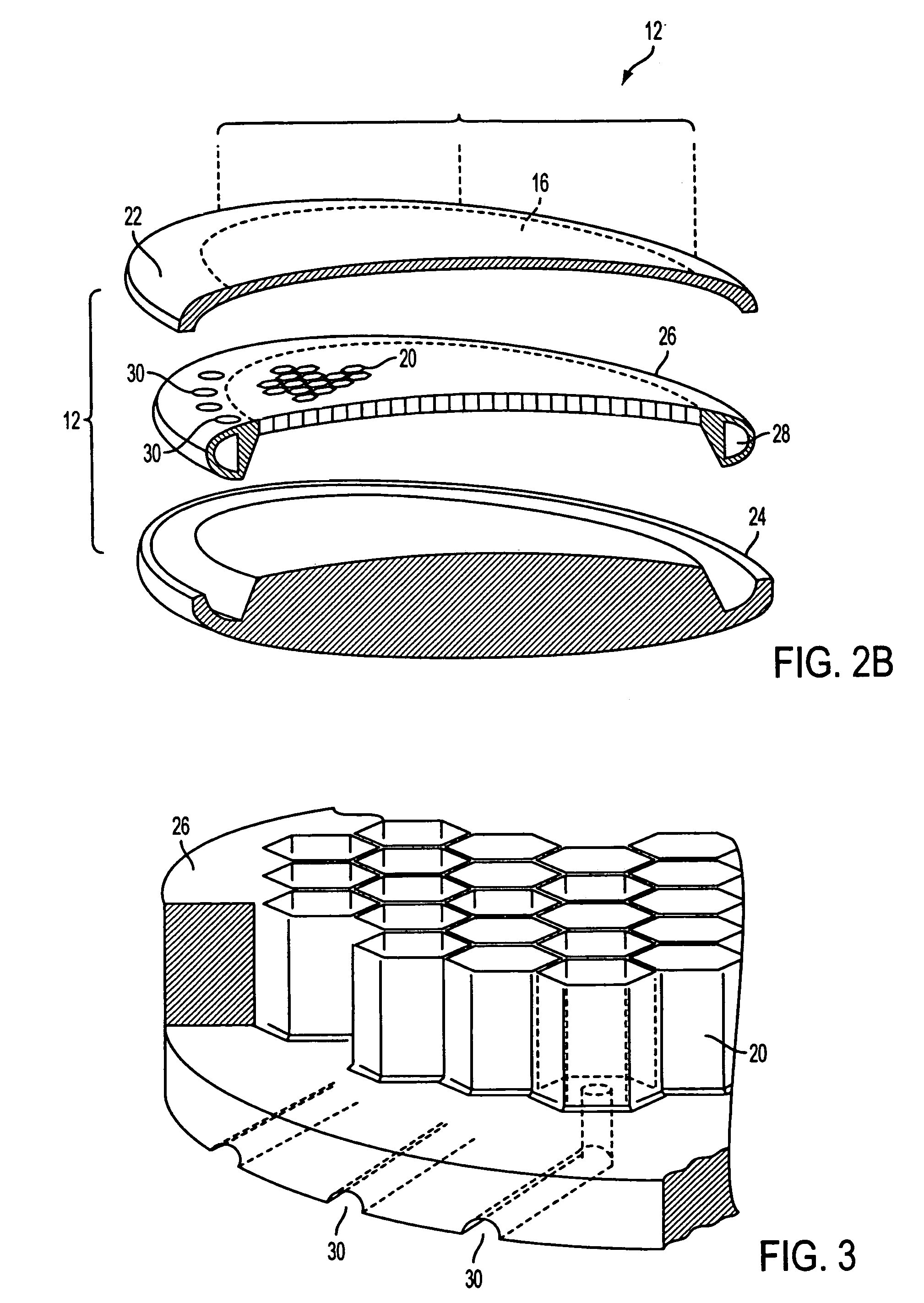
[0038]In accordance with the principles of the present invention, methods and apparatus are provided wherein a lens has a locally deformable surface coupled to a one or more independently actuable fluid-filled actuators or cells. The volume within, and deformation of, the fluid-filled cells is controlled by selective actuation, using an external power source, of individual flow control mechanisms coupled between the cells and one or more reservoirs.

[0039]Subsequent to implantation of the IOL and healing of the ...


PUM


Abstract

A lens is provided that having optical parameters that may be adjusted in-situ, and is particularly useful as an IOL for use in cataract patients that require an adjustment in the optical power of the lens post-implantation. In one embodiment, the lens body carries an array of interior fluid-filled cells in which fluid is controllably moved upon application of energy from an external source to move a fluid media into or out of the cells to thereby alter the lens surface shape.

Description

REFERENCE TO RELATED APPLICATIONS[0001]This application claims the benefit of priority from U.S. provisional application 60 / 428,173, filed Nov. 20, 2002 (Docket No. S-APV-001) titled “Lens System and Method for Power Adjustment”.FIELD OF THE INVENTION[0002]The present invention relates to lenses having optical parameters that are adjustable in-situ. More particularly, the invention has applications in IOLs for in-capsule implantation for cataract patients, and in contact lenses, wherein an external energy source is applied to the lens to control movement of fluid media within interior cells of the lens, thereby altering the lens curvature to correct aberrations.BACKGROUND OF THE INVENTION[0003]Cataracts are a major cause of blindness-in the world and the most prevalent ocular disease. Visual disability from cataracts accounts for more than 8 million physician office visits per year. When the disability from cataracts affects or alters an individual's activities of daily living, surg...

Claims


Application Information

Patent Timeline
Patent Type & Authority Patents(United States)
IPC IPC(8): G02B1/06A61F2/16G02C7/04
CPCA61F2/16A61F2/1613G02C7/085A61F2/1648G02C7/04A61F2/1635A61F2/1601
Inventor ESCH, VICTOR C.SHADDUCK, JOHN H.
Owner ALCON INC
Why Eureka
Try Eureka