

Variable magnification optical system
- Summary
- Abstract
- Description
- Claims
- Application Information
AI Technical Summary
Benefits of technology
Problems solved by technology
Method used
Image

Examples
examples
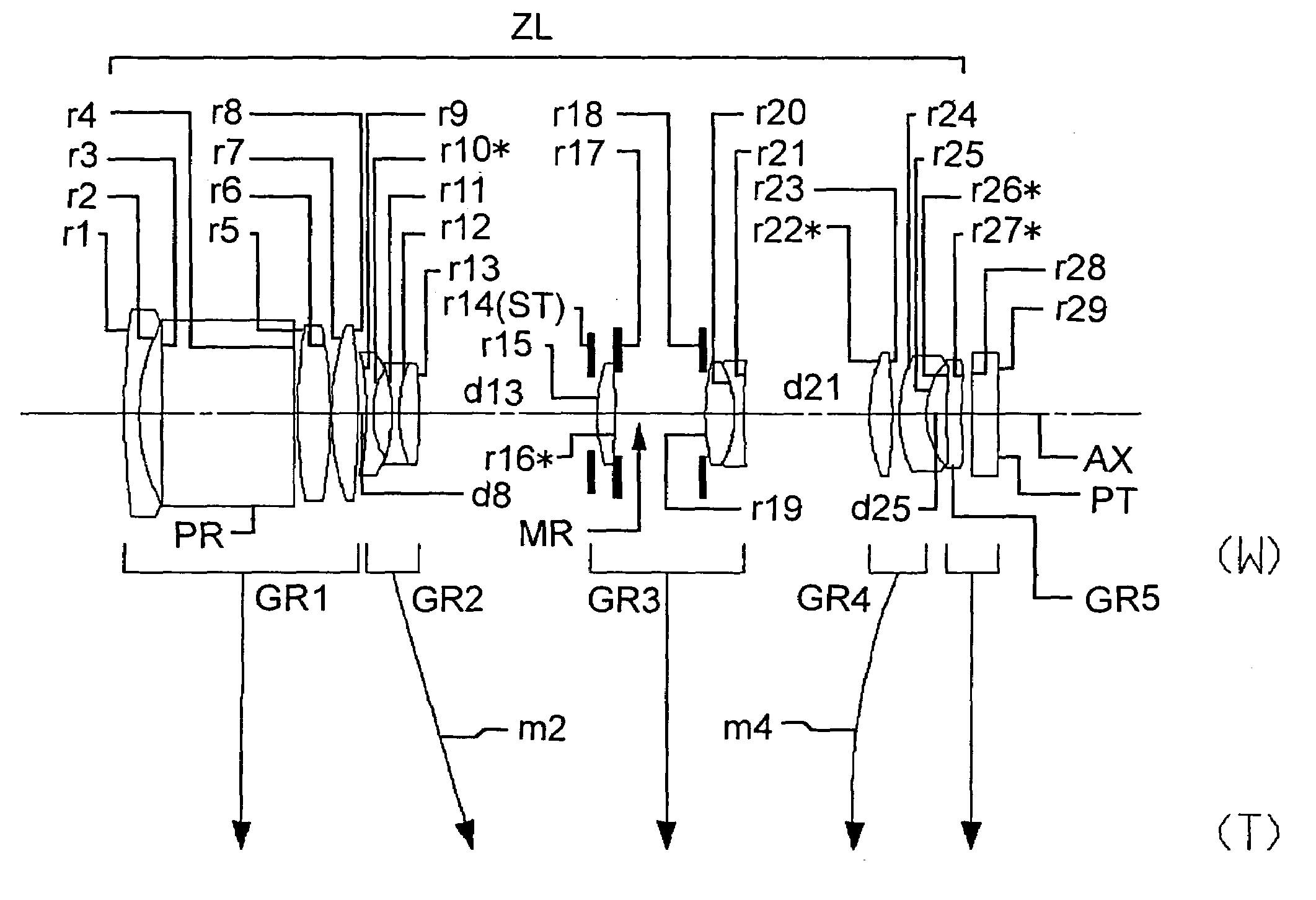
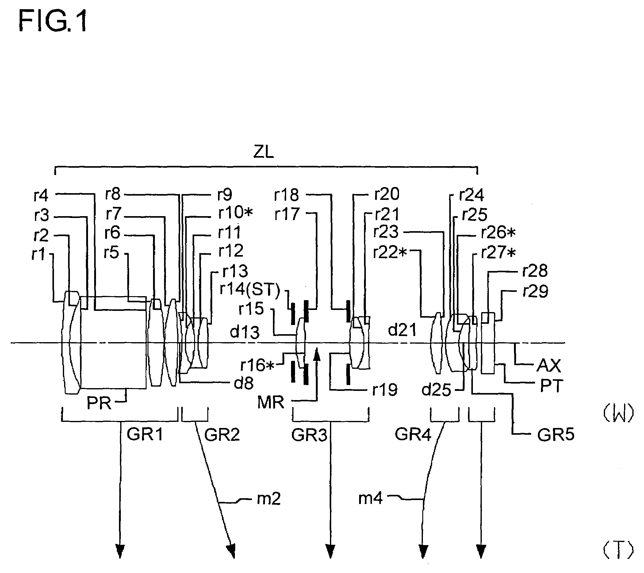
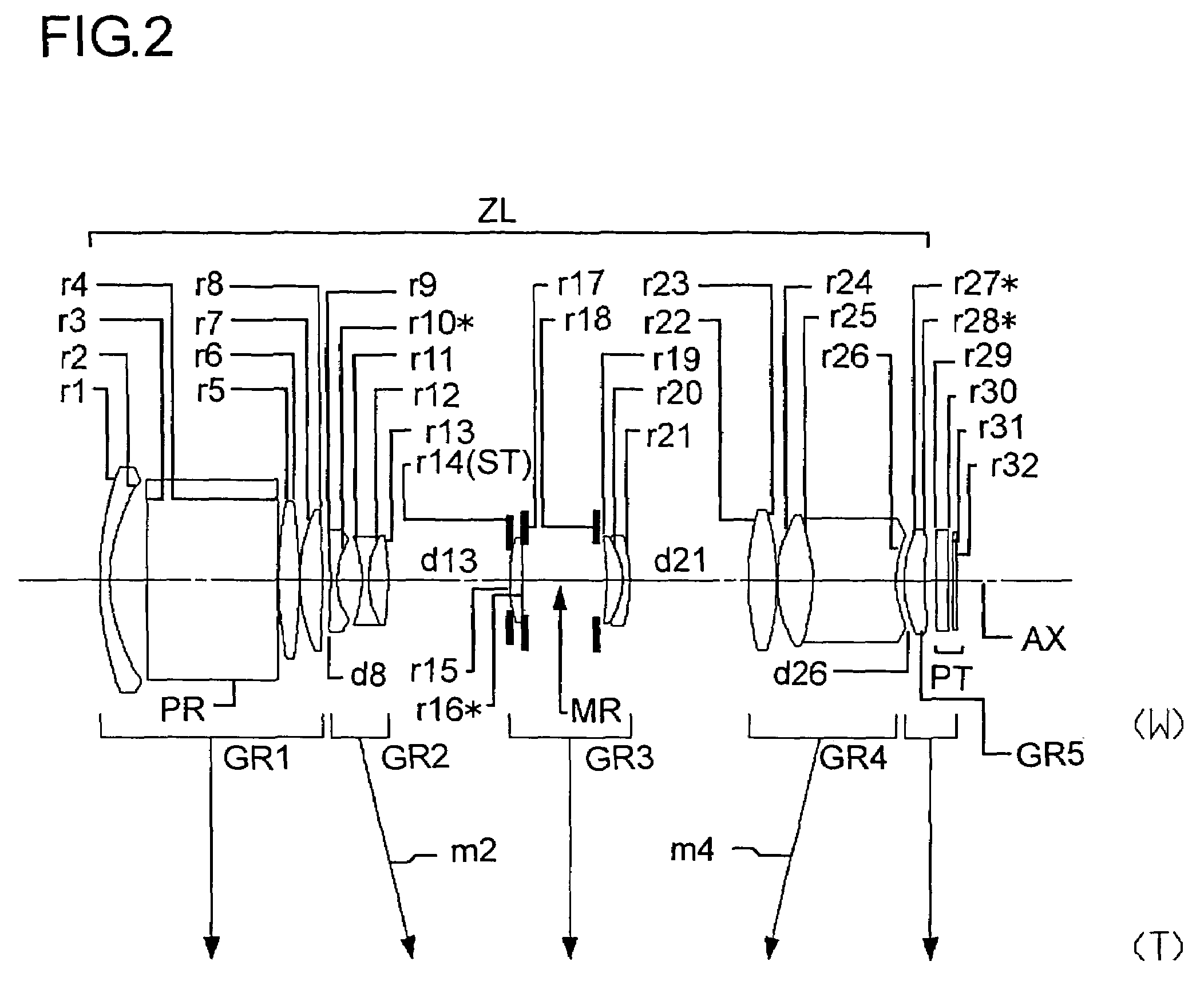
[0078]Hereinafter, the construction and other features of practical examples of the zoom lens system embodying the present invention will be presented with reference to their construction data and other data. Examples 1 to 5 presented below are numerical examples corresponding to the first to fifth embodiments, respectively, described hereinbefore, and therefore the optical construction diagrams (FIGS. 1 to 5) of the first to fifth embodiments also show the lens construction of Examples 1 to 5, respectively.
[0079]Tables 1 to 10 show the construction data of Examples 1 to 5. Table 11 shows the values of the conditional formulae as actually observed in each example. In the basic optical construction (with i representing the surface number) as shown in tables 1, 3, 5, 7, and 9, ri (i=1, 2, 3, . . . ) represents the radius of curvature (in mm) of the i-th surface from the object side, di (i=1, 2, 3, . . . ) represents the axial distance (in mm) between the i-th and (i+1)-th surfaces fro...
PUM
 Abstract
Description
Claims
Application Information