Slider fly control

a technology of fly control and sliding rod, which is applied in the direction of maintaining the head carrier alignment, recording information storage, instruments, etc., can solve the problems of air bearing itself not maintaining proper clearance with the disc, damage to the head or the disc, and loss of valuable data

Inactive Publication Date: 2006-06-27
SEAGATE TECH LLC
View PDF20 Cites 49 Cited by
  • Summary
  • Abstract
  • Description
  • Claims
  • Application Information

AI Technical Summary

Problems solved by technology

If the quality of the disc or the slider is poor, occasional rubbing or sharp contact may occur between the disc and the slider, leading to damage to the head or to the disc, and possibly the loss of valuable data.
However, in disc drives employing sliders operating at extremely low fly heights, the air bearing itself cannot maintain proper clearance with the disc.
This is because of several factors including mean losses from disc glide avalanche, carbon overcoats, pole tip recession and lubricant coating on the disc surface that leave insufficient space for the air-bearing surface to provide the necessary fly height variation.
However, sensing the fly height in real time during disc read / write operations may interfere with the read / write process because the fly height sensor and the read / write head are usually in close proximity with each other.
In addition, dynamically sensing fly height during the reading and writing of data adds complexity to the read / write process.

Method used


Image

  • Slider fly control
  • Slider fly control
  • Slider fly control

Examples


Embodiment Construction

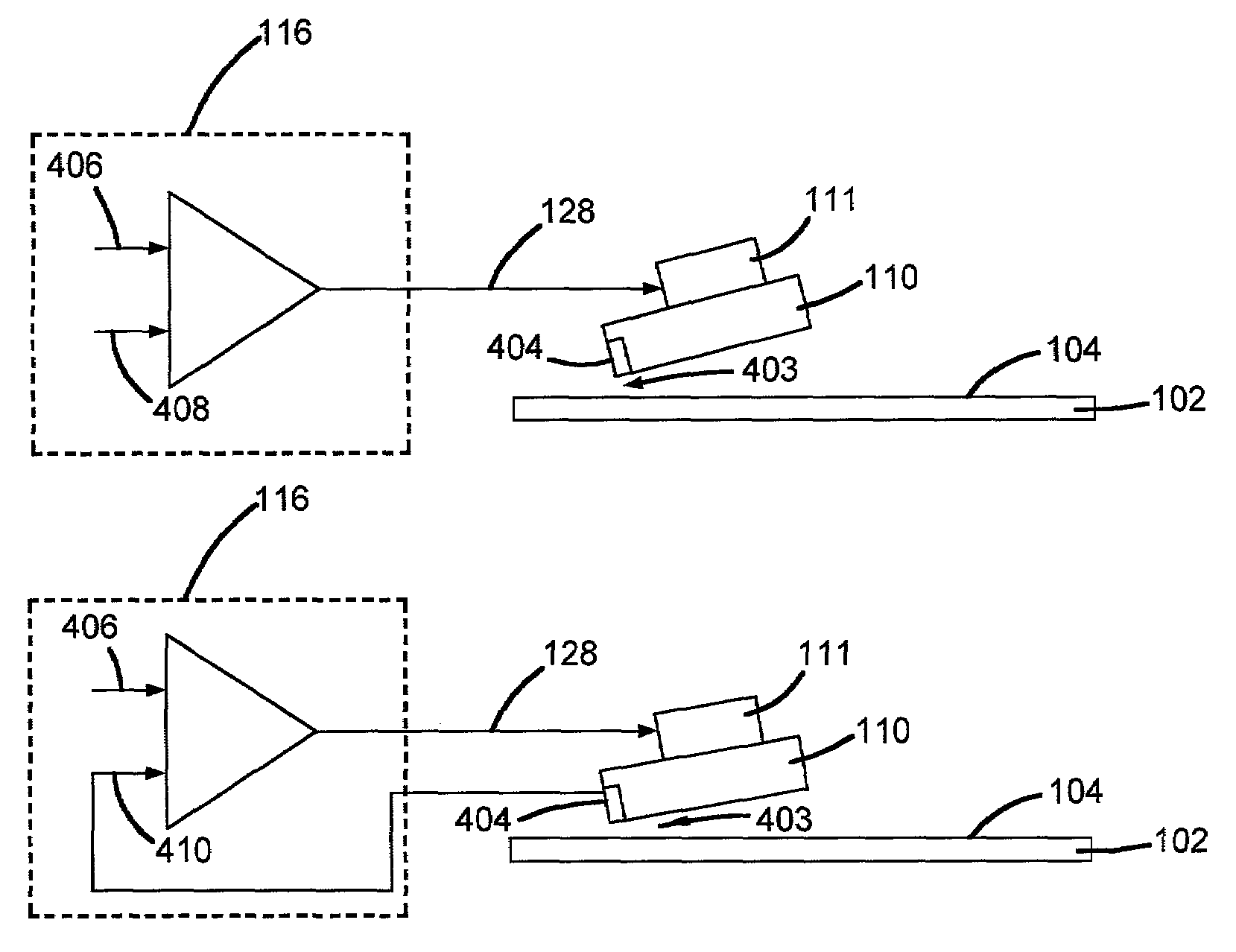
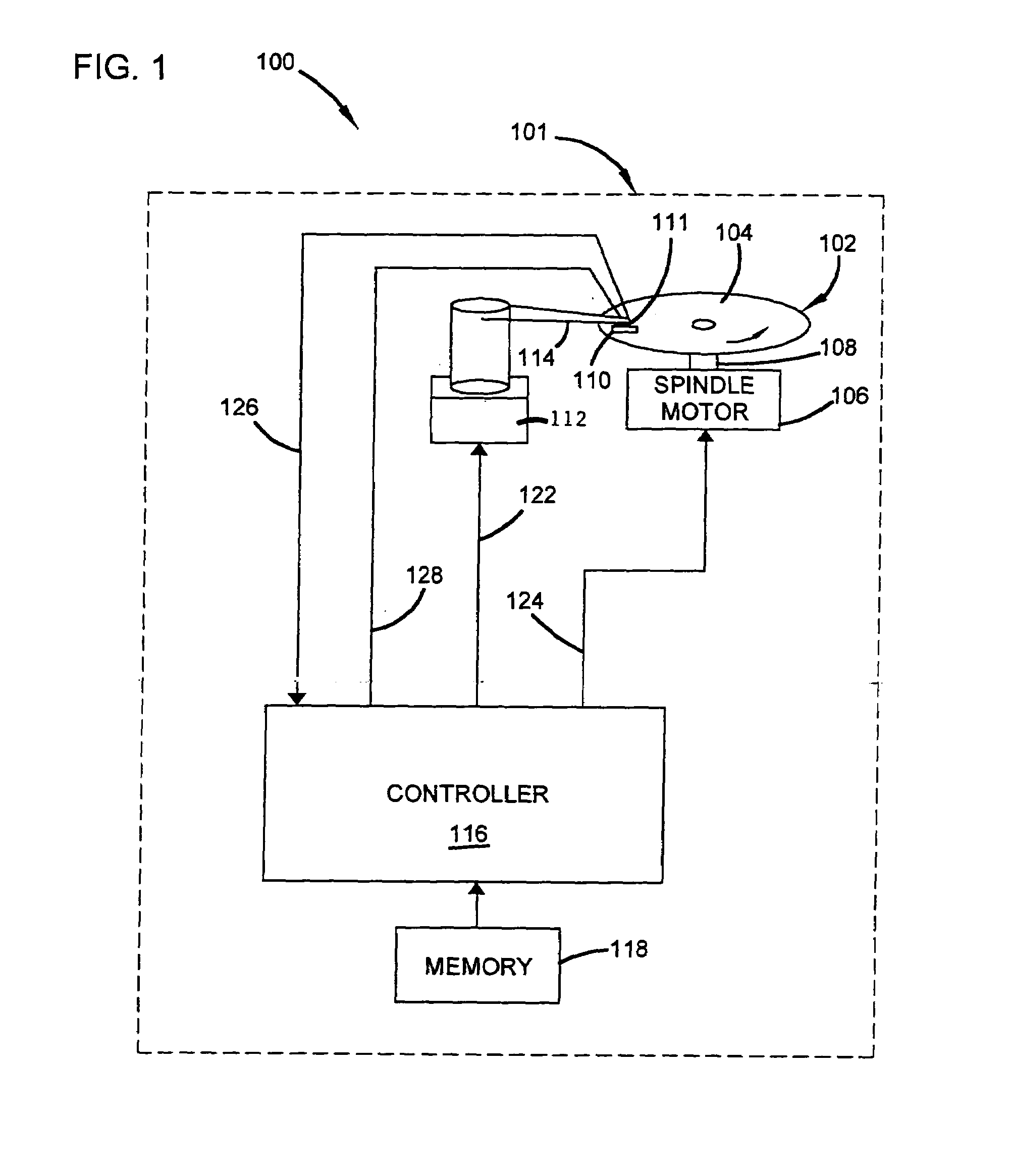
[0015]FIG. 1 is a very simplified block diagram of a disc storage system 100 in accordance with an embodiment of the present invention. Disc storage system 100 includes a housing 101 and a disc storage medium 102 having a data surface 104. Disc 102 is coupled to a spindle motor 106 through a spindle 108. A transducing head, supported by slider 110, is positioned relative to surface 104 for reading and writing information onto surface 104. Slider 110 is coupled to an actuator 112 through an armature 114. The transducer on slider 110 can read or write information on a desired location on surface 104 by moving slider 110 with actuator 112 in a manner to position the transducer radially while disc 102 rotates.

[0016]System 100 further includes a controller 116 that controls the radial position of slider 110 by energizing actuator 112 over control connection 122. Further, controller 116 controls operation of motor 106 over control connection 124. Thus, controller 116 can position slider 1...


PUM

PropertyMeasurementUnit
heightaaaaaaaaaa
heightaaaaaaaaaa
fly heightaaaaaaaaaa

Abstract

A disc drive data storage system is disclosed that includes a disc storage medium having a disc surface. The system also includes an armature and a slider coupled to the armature. The slider supports a transducer head that communicates with the disc storage medium. The slider flies above the disc surface and positions the transducer head proximate the disc surface. Data representing a topography map of the disc surface is stored in a memory. A controller controls the fly height of the slider above the disc surface as a function of the topography map of the disc surface.

Description

CROSS-REFERENCE TO RELATED APPLICATION[0001]This application claims priority to U.S. Provisional Application No. 60 / 305,794, filed Jul. 16, 2001 and entitled “CAPACITANCE MAPPING AND STORAGE OF DISC TOPOGRAPHY FOR ACTIVE FLY CONTROL,” which is herein incorporated by reference.FIELD OF THE INVENTION[0002]The present invention relates to data storage systems. More specifically, the present invention relates to a system for active fly height control of a slider used in a disc storage system.BACKGROUND OF THE INVENTION[0003]Disc storage systems are known in the art and are used to store information for later retrieval. Such disc storage systems include a rotating disc which carries information thereon. A transducing head is positioned over a surface of the disc while the disc rotates at high speed. The head is carried on a slider which is designed to “fly” just over the surface of the rotating disc, the separation between the slider and the disc being maintained by a film of air (air be...

Claims


Application Information

Patent Timeline
Patent Type & Authority Patents(United States)
IPC IPC(8): G11B5/02G11B21/02G11B5/58G11B5/60G11B33/10
CPCG11B5/58G11B5/6005G11B33/10
Inventor RIDDERING, JASON W.BONIN, WAYNE A.BOUTAGHOU, ZINE-EDDINE
Owner SEAGATE TECH LLC
Why Eureka
Try Eureka