Protection device with lockout test

a technology of protection device and lockout test, which is applied in the direction of emergency protective arrangement for limiting excess voltage/current, protective switch details, protective switch operating/release mechanisms, etc., and can solve the problems of life-threatening current flowing through the body of the person, limited current through this type of fault, and heat nearby combustible materials

Inactive Publication Date: 2006-06-27
PASS SEYMOUR
View PDF18 Cites 43 Cited by
  • Summary
  • Abstract
  • Description
  • Claims
  • Application Information

AI Technical Summary

Benefits of technology

[0016]According to another embodiment of the invention, the present invention is directed to a protective device that includes a plurality of line terminals configured to be connected to an electrical distribution system, and a plurality of load terminals configured to be connected to at least one load. The device includes a fault detection circuit coupled to the plurality of line terminals and the plurality of load terminals. The fault detection circuit is configured to detect at least one fault condition. A power interruption circuit coupled to the fault detection circuit, the power interruption circuit including a set of movable contacts configured to decouple the plurality of line terminals from the plurality of load terminals in response to the fault detection circuit detecting the at least one fault condition. A reset mechanism is coupled to the power interruption circuit and configured to actuate the movable conta

Problems solved by technology

In the absence of a GFCI, life threatening amounts of current could flow through the body of the person.
The current through this type of fault is limited by the impedance of the load.
Since the fault is in series with the load, this type of fault has also been known as a “series arc fault.” In the absence of an AFCI, the sputtering currents associated with an arc fault, whether of the parallel, series or some other type, could heat nearby combustibles and result in fire.
Any of these components may fail and cause the circuit interrupter to fail to remove power from the load side of the protective device to interrupt the fault.
Since the protective device comprises electronic and mechanical components, failure may occur because of normal aging of th

Method used


Image

  • Protection device with lockout test
  • Protection device with lockout test
  • Protection device with lockout test

Examples


Embodiment Construction

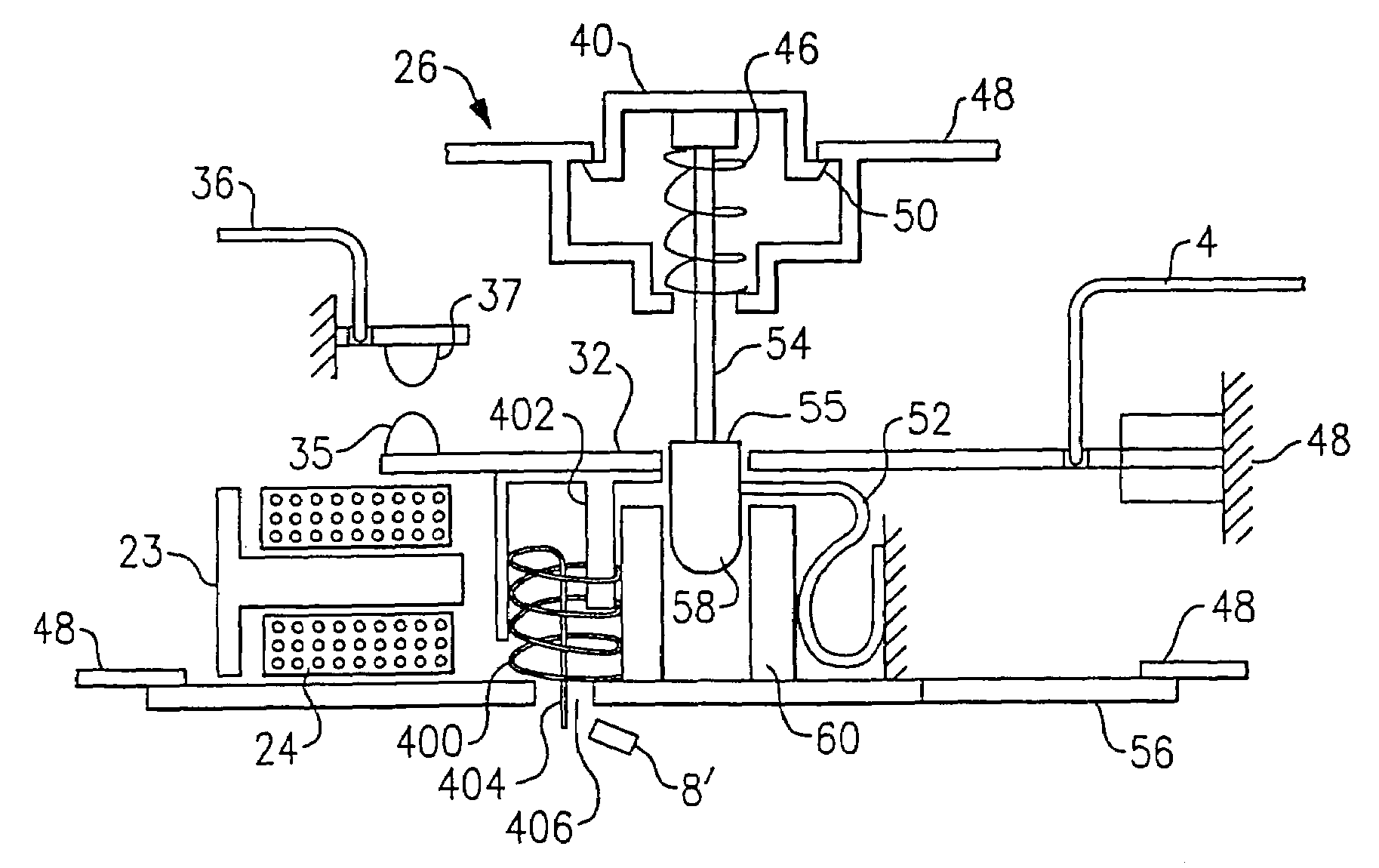
[0033]Reference will now be made in detail to the present exemplary embodiments of the invention, examples of which are illustrated in the accompanying drawings. Wherever possible, the same reference numbers will be used throughout the drawings to refer to the same or like parts. An exemplary embodiment of the GFCI of the present invention is shown in FIGS. 4–13 and is designated generally throughout by reference numeral 2.

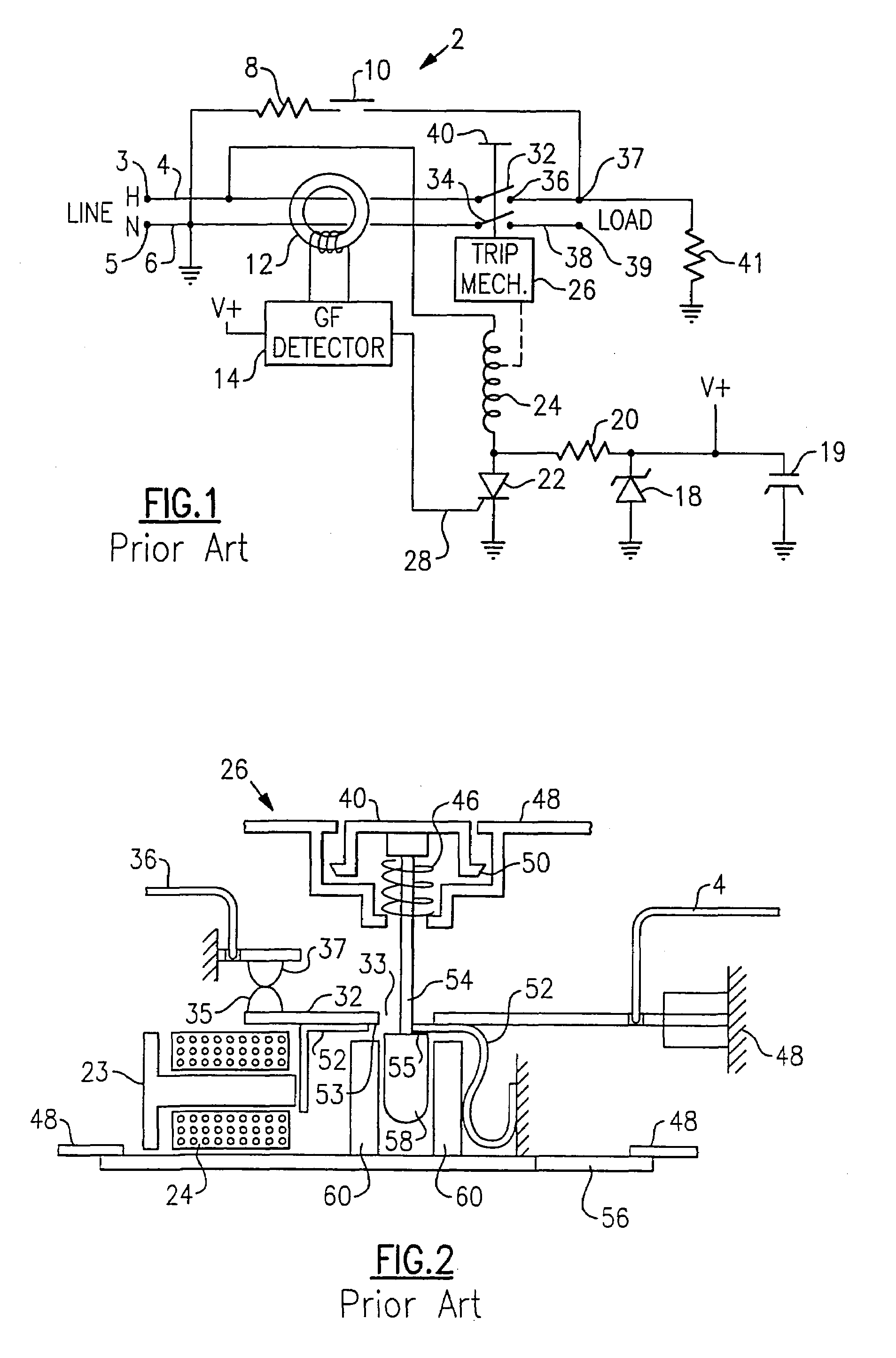
[0034]Referring to FIG. 4, a partial sectional view of a mechanical implementation of an embodiment of the invention is shown. A resistor 8′, shown schematically in FIG. 1 as resistor 8, is designed to withstand self-heating that results from each depression of contact 10, which causes current to flow through resistor 8′ for the expected trip time of the GFCI. For example, resistor 8′ for a 6 mA GFCI coupled to a 120 VAC supply is required by UL to be 15 KOhms, which dissipates nominally 0.96 Watts during each trip time interval. In particular, resistor 8′ must su...


PUM


Abstract

The present invention is directed to a protective device that includes a plurality of line terminals configured to be connected to an electrical distribution system, and a plurality of load terminals configured to be connected to at least one load. The device includes a fault detection circuit coupled to the plurality of line terminals and the plurality of load terminals. The fault detection circuit is configured to detect at least one fault condition. A power interruption circuit coupled to the fault detection circuit, the power interruption circuit including a set of movable contacts configured to decouple the plurality of line terminals from the plurality of load terminals in response to the fault detection circuit detecting the at least one fault condition. A reset mechanism is coupled to the power interruption circuit and configured to actuate the movable contacts to re-couple the plurality of line terminals to the plurality of load terminals. A lock-out mechanism is coupled to the reset mechanism. The lockout mechanism is configured to disable the reset mechanism in a lock-out state. A test circuit is coupled to the fault detection circuit and the lock-out mechanism. The test circuit is configured to provide a simulated fault signal to the fault detection circuit. The test circuit is configured to drive the lock-out mechanism from an unlocked state to the lock-out state if the fault detection circuit and/or power interruption circuit fails to respond to the simulated fault signal within a predetermined period of time.

Description

CROSS-REFERENCE TO RELATED APPLICATIONS[0001]This is a continuation of U.S. patent application Ser. No. 10 / 263,028 filed on Oct. 2, 2002, now abandoned the content of which is relied upon and incorporated herein by reference in its entirety, and the benefit of priority under 35 U.S.C. §120 is hereby claimed. This application claims the benefit of U.S. provisional application Ser. No. 60 / 326,531 filed Oct. 2, 2001.FIELD OF THE INVENTION[0002]This invention relates generally to the field of devices for protecting electrical circuits in the event of faults, and more particularly to a device that protects from arc faults and ground faults, which is provided with a manual test feature that permanently denies power to the protected circuit should the test fail.BACKGROUND OF THE INVENTION[0003]The electrical distribution system is defined to include the circuit breaker, branch circuit conductors, wiring devices, cord sets or extension cords, and electrical conductors within an appliance. A...

Claims


Application Information

Patent Timeline
IPC IPC(8): H01H83/04H01H71/20H02H3/05H02H3/33
CPCH01H71/20H01H83/04H02H3/05H01H2071/044H02H3/338H02H3/335H01H2083/201
Inventor RADOSAVLJEVIC, DEJANPACKARD, THOMAS N.MACBETH, BRUCE F.
Owner PASS SEYMOUR
Why Eureka
Try Eureka