Telephone set with a handset having a mouthpiece and/or an earpiece

a technology of earpieces and handsets, which is applied in the field of telephone sets with mouthpieces and/or earpieces, can solve the problems of no longer being able to jam against the sides of the sheath, and achieve the effects of reducing the overall width of the hand-held radio telephone, preventing swinging or rattling, and improving insertion

Inactive Publication Date: 2006-06-27
PEIKER ANDREAS
View PDF66 Cites 37 Cited by
  • Summary
  • Abstract
  • Description
  • Claims
  • Application Information

AI Technical Summary

Benefits of technology

[0010]In one preferred embodiment, the swing-out insertion piece of the hand-held shell, which is designed as a sort of sheath, contains at least one collar piece on which the lower portion of a hand-held radio telephone rests when the insertion piece is swung into line. When the unit is swung out around a swiveling axis that holds the insertion piece, the front (sheath) edge is moved both forward and downward in a relative motion to the preferably fixed collar piece. This permits the hand-held radio telephone to be easily removed. The collar piece acts as an “ejector.” The lower portion of the hand-held radio telephone is shifted relatively forward and upward, but is held fast laterally. In its removal, however, it no longer can be jammed against the sides of the sheath. The sides of the sheath can thus no longer be damaged, specifically its upper edge cannot be broken off.
[0018]For hands-free operation it is particularly advantageous for the hand-held shell and the console to be designed such that when the shell is placed on the console, the keypad on the hand-held radio telephone is accessible. Thus, the shell need not be removed from the console to permit operation of the telephone.
[0022]In one preferred embodiment of the invention, the hand-held shell is equipped with a swing-out insertion piece for the hand-held radio telephone. This serves to ensure a particularly user-friendly insertion and removal of the handheld radio telephone. The insertion can also be improved if the insertion piece remains arrested in its swung-out position of approximately 10*. This swung-out position is preferably maintained by a spring, in order to prevent swinging or rattling brought on by vibrations or shaking of the automobile. In a further preferred design variation, the insertion piece is designed to be sheath-like, wherein the rear panel of the sheath extends upward over the edge of the sheath. This portion of the rear panel of the sheath serves as a guiding rail for the handheld radio telephone to be partially inserted in the sheath opening. The guiding rail can be swung out toward the front with the insertion piece, or can remain in a fixed position. The swiveling axis that permits this swinging out extends nearly perpendicular to the lengthwise axis of the sheath. It may be positioned either within the sheath or above the sheath.
[0023]The hand-held shell may, as is illustrated in FIGS. 1 through 4, be shaped like a shell that will hold the hand-held radio telephone. It may, however, also be dumbbell-shaped, with a recessed area for the upper and the lower portions of the hand-held radio telephone, and a narrow connecting strip between these two portions. This design reduces the overall width of the hand-held radio telephone placed in the “hand-held shell”; this presents a advantage particularly for women having delicate, small hands. The connecting strip may be curved in an ergonomic design.

Problems solved by technology

In its removal, however, it no longer can be jammed against the sides of the sheath.

Method used


Image

  • Telephone set with a handset having a mouthpiece and/or an earpiece
  • Telephone set with a handset having a mouthpiece and/or an earpiece
  • Telephone set with a handset having a mouthpiece and/or an earpiece

Examples


Embodiment Construction

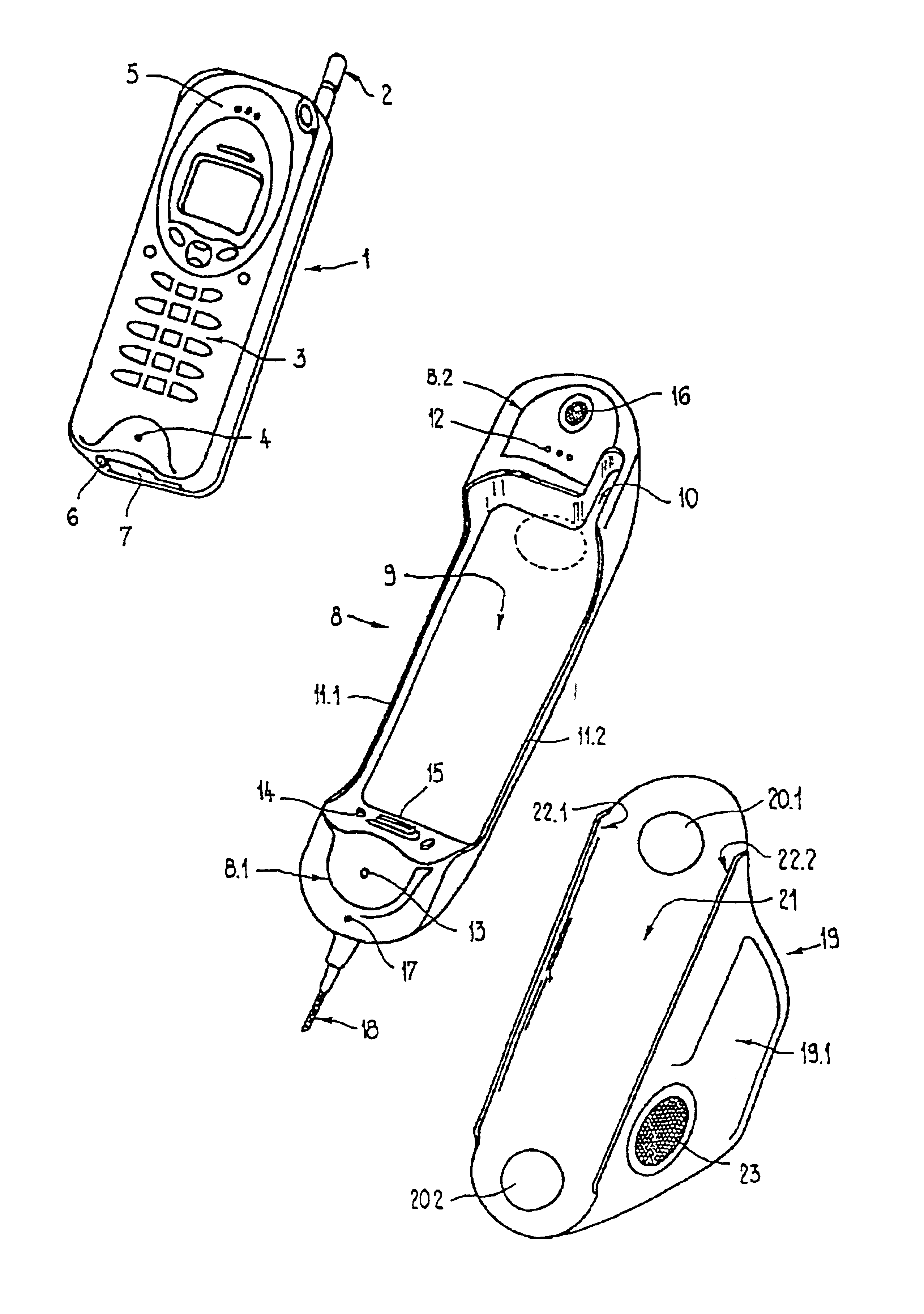
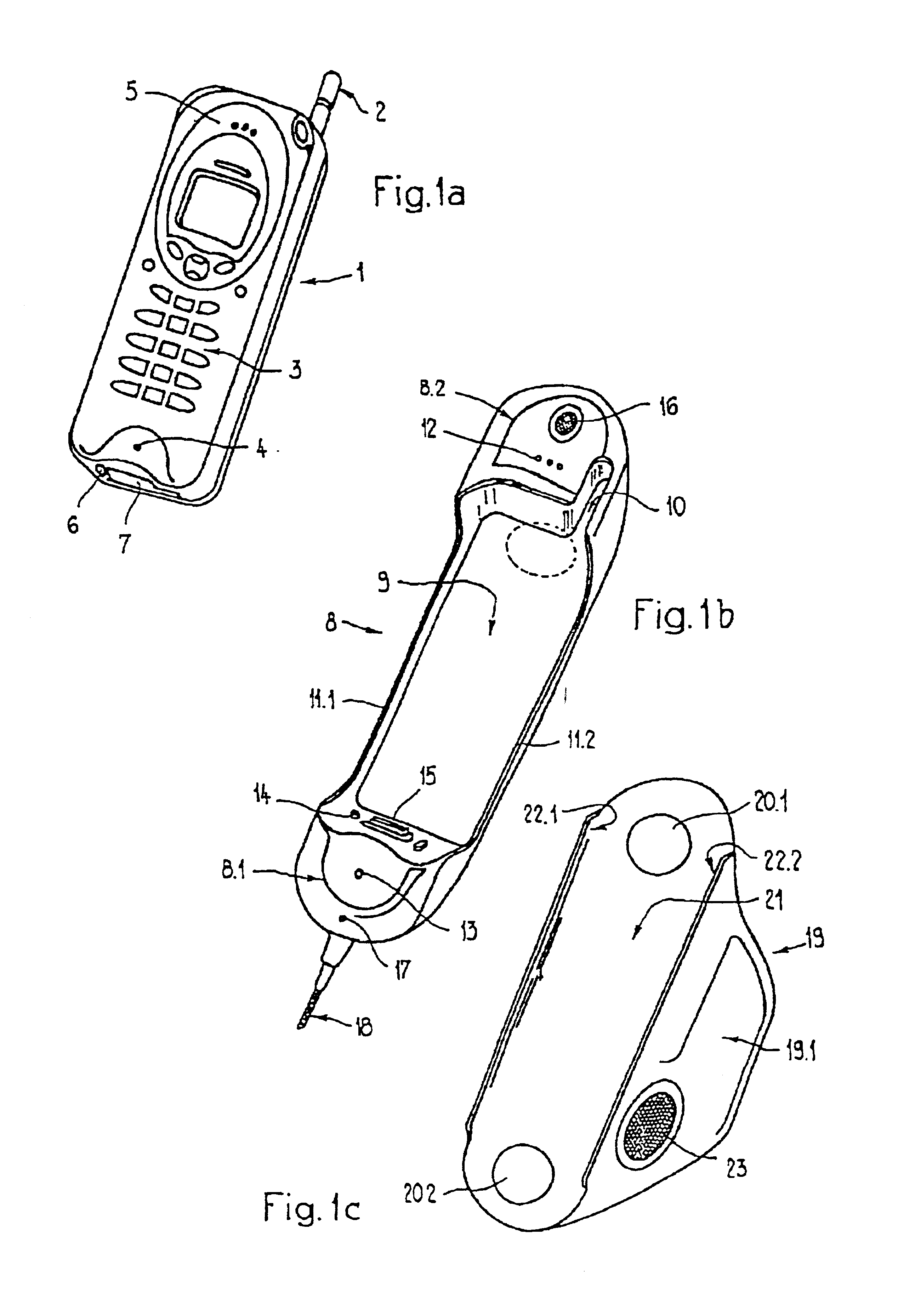
[0043]FIG. 1a shows a schematic, perspective illustration of a hand-held radio telephone 1. This telephone is rectangular, when viewed from the front, and is relatively narrow in thickness. One side of the upper end contains an antenna 2. One surface of the lower end contains a main connection 6 and a connector plug 7, as part of a detachable interface. The hand-held radio telephone 1 is supplied with power via the main connection 6. If the hand-held radio telephone 1 is equipped with an accumulator, this can be charged via the main connection 6. The function of the connector plug 7 will be described in greater detail below.

[0044]In a traditional manner, the hand-held radio telephone is equipped with a keypad 3, a microphone 4 (as the mouthpiece) and an ear-piece 5.

[0045]The hand-held radio telephone 1 can be inserted into a hand-held shell 8 in accordance with the invention, as is schematically illustrated, for example, in FIG. 1b. The handheld shell 8 is, for example, designed as ...


PUM


Abstract

A telephone assembly including a handset containing a microphone and / or a receiver. The handset is equipped with a space designed to hold a hand-held cordless telephone that can be removed from the handset, and for electrical coupling of the cordless telephone.

Description

BACKGROUND OF THE INVENTION[0001]Telephone assemblies for mounting in vehicles vary widely in their design.[0002]One mounting fixture for a transportable mobile telephone, known in the art from the German utility model G 93 11294.7, is comprised basically of two opposing side panels and a base plate that connects them to one another. The mobile telephone is placed in between the side panels and rests on the base plate. It is held securely by a positive- or non-positive lock connection. The mounting fixture is fastened with screws, for example, to the side panel of a center console between the driver's seat and the passenger's seat inside the vehicle.[0003]A mounting fixture for a mobile radio telephone, known in the art from EP 0 545 670 A2, is comprised of two interlocking components. The outer component is firmly fastened with screws to a base. The inner component represents a sort of seesaw into which the hand-held radio telephone can be inserted from the front. The seesaw can be...

Claims


Application Information

Patent Timeline
Patent Type & Authority Patents(United States)
IPC IPC(8): H04M1/00B60R11/00B60R11/02H04M1/04H04M1/11H04M1/60H04Q7/32
CPCB60R11/0241H04M1/6075B60R11/0217B60R11/0247B60R2011/0005B60R2011/0052B60R2011/0071B60R2011/0075B60R2011/0078H04M1/6041B60R2011/0059
Inventor PEIKER, ANDREAS
Owner PEIKER ANDREAS
Why Eureka
Try Eureka