Double diffraction grating planar lightwave circuit

a technology of planar lightwave circuit and double diffraction grating, which is applied in the direction of optical multiplex, electrical apparatus, instruments, etc., can solve the problems of difficulty, no practical means of addressing a wide wavelength range, and the typical triplexer requirements present considerable challenges to conventional plc design techniques

Inactive Publication Date: 2006-06-27
ENABLENCE
View PDF14 Cites 29 Cited by
  • Summary
  • Abstract
  • Description
  • Claims
  • Application Information

AI Technical Summary

Problems solved by technology

Typical triplexer requirements present considerable challenges to conventional PLC design techniques.
The difficulty arises due to the operational passbands at these wavelengths.
In the prior art, especially those designs using a single diffractive structure in a PLC, there is no practical means of addressing a wide wavelength range (˜1250 nm to 1600 nm) with channels having substantially different passbands.
Unfortunately, the assembly of such a device is extremely labor intensive requiring all of the elements to be aligned with very low tolerances.
Unfortunately, all of these solutions still involve the alignment of TFFs with TO cans.

Method used


Image

  • Double diffraction grating planar lightwave circuit
  • Double diffraction grating planar lightwave circuit
  • Double diffraction grating planar lightwave circuit

Examples


Embodiment Construction

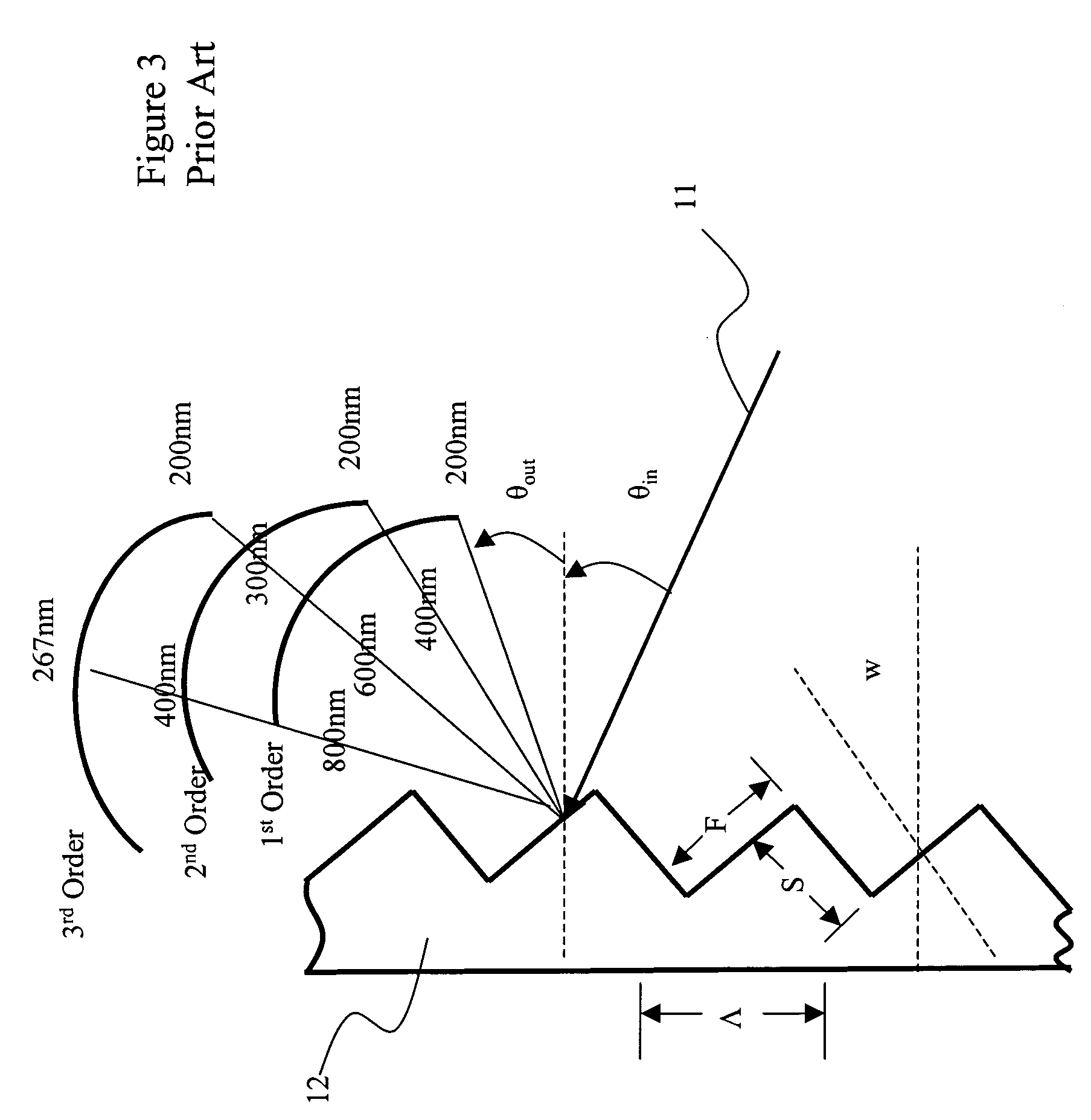
[0026]A planar waveguide reflective diffraction grating includes an array of facets arranged in a regular sequence. The performance of a simple diffraction grating is illustrated with reference to FIG. 3. An optical beam 11, with a plurality of wavelength channels λ1, λ2, λ3 . . . , enters a diffraction grating 12, with grading pitch Λ and diffraction order m, at a particular angle of incidence θin. The optical beam is then angularly dispersed at an angle θout depending upon wavelength and the order, in accordance with the grating equation:

mλ=Λ(sin θin+sin θout)  (1)

[0027]From the grating equation (1), the condition for the formation of a diffracted order depends on the wavelength λN of the incident light. When considering the formation of a spectrum, it is necessary to know how the angle of diffraction θNout varies with the incident wavelength θin. Accordingly, by differentiating the equation (1) with respect to θNout, assuming that the angle of incidence θin is fixed, the followin...


PUM


Abstract

The invention relates to a planar lightwave circuit including a pair of opposed concave reflective diffraction gratings sharing the same focal line, which separates first and second slab waveguide regions. The ends of input and output waveguides are positioned along the focal line for launching and receiving light directed by one or both of the diffraction gratings. The invention enables light within in a certain wavelength range to be launched from an input waveguide, directed by a single diffraction grating, and output waveguides, all within a single slab waveguide region, while light within another wavelength range will be directed from one diffraction grating to another for output waveguides in a different slab waveguide region.

Description

CROSS-REFERENCE TO RELATED APPLICATIONS[0001]The present invention claims priority from U.S. Patent Applications Nos. 60 / 555,686 filed Mar. 24, 2004, and 60 / 557,711 filed Mar. 31, 2004, which are incorporated herein by reference.TECHNICAL FIELD[0002]The present invention relates to a double diffraction grating planar lightwave circuit, and in particular to a planar lightwave circuit (PLC) optical triplexer for use in fiber-to-the-home (FTTH) optical networks.BACKGROUND OF THE INVENTION[0003]A triplexer or Voice-Data-Video (VDV) processor serves as an optical gateway from an FTTH optical network into a subscriber's home. A triplexer is an extremely compact and low-cost access device capable of receiving two high-speed channels (e.g. 1490 nm for telephone & internet, and 1550 nm for video), while simultaneously transmitting on a third channel (e.g. 1310 for information out). All these signals are multiplexed onto a single optical fiber for simple installation.[0004]Typical triplexer r...

Claims


Application Information

Patent Timeline
Patent Type & Authority Patents(United States)
IPC IPC(8): G02B6/34H04J14/02G02B6/12G02B6/124G02B6/26G02B6/42
CPCG02B6/124G02B6/12007
Inventor BIDNYK, SERGEBALAKRISHNAN, ASHOKPEARSON, MATT
Owner ENABLENCE
Why Eureka
Try Eureka