Compressed code decoding device and audio decoding device

a code decoding and code decoding technology, applied in the field of compressed code decoding devices and audio decoding devices, can solve the problems of large storage capacity, high cost of memory types, and inability to reproduce audio signals in synchronization with other signals, and achieve the effect of reducing the cost of memory used, improving the processing capability of audio signals, and small memory capacity

Inactive Publication Date: 2006-06-27
PANASONIC CORP
View PDF18 Cites 76 Cited by
  • Summary
  • Abstract
  • Description
  • Claims
  • Application Information

AI Technical Summary

Benefits of technology

[0052]Thus, the invention described herein makes possible the advantages of: (1) providing a compressed code decoding device for decoding and outputting compressed codes of audio signals in synchronization with timer and video signals by using a buffer of a relatively small memory capacity; and (2) providing a

Problems solved by technology

However, the conventional device does not reproduce the audio signals in synchronization with other signals such as video signals and timer signals which serve as reference time for reproduction, but merely outputs the audio signals at a separate timing.
There is also a problem that a storage cap

Method used


Image

  • Compressed code decoding device and audio decoding device
  • Compressed code decoding device and audio decoding device
  • Compressed code decoding device and audio decoding device

Examples


example 1

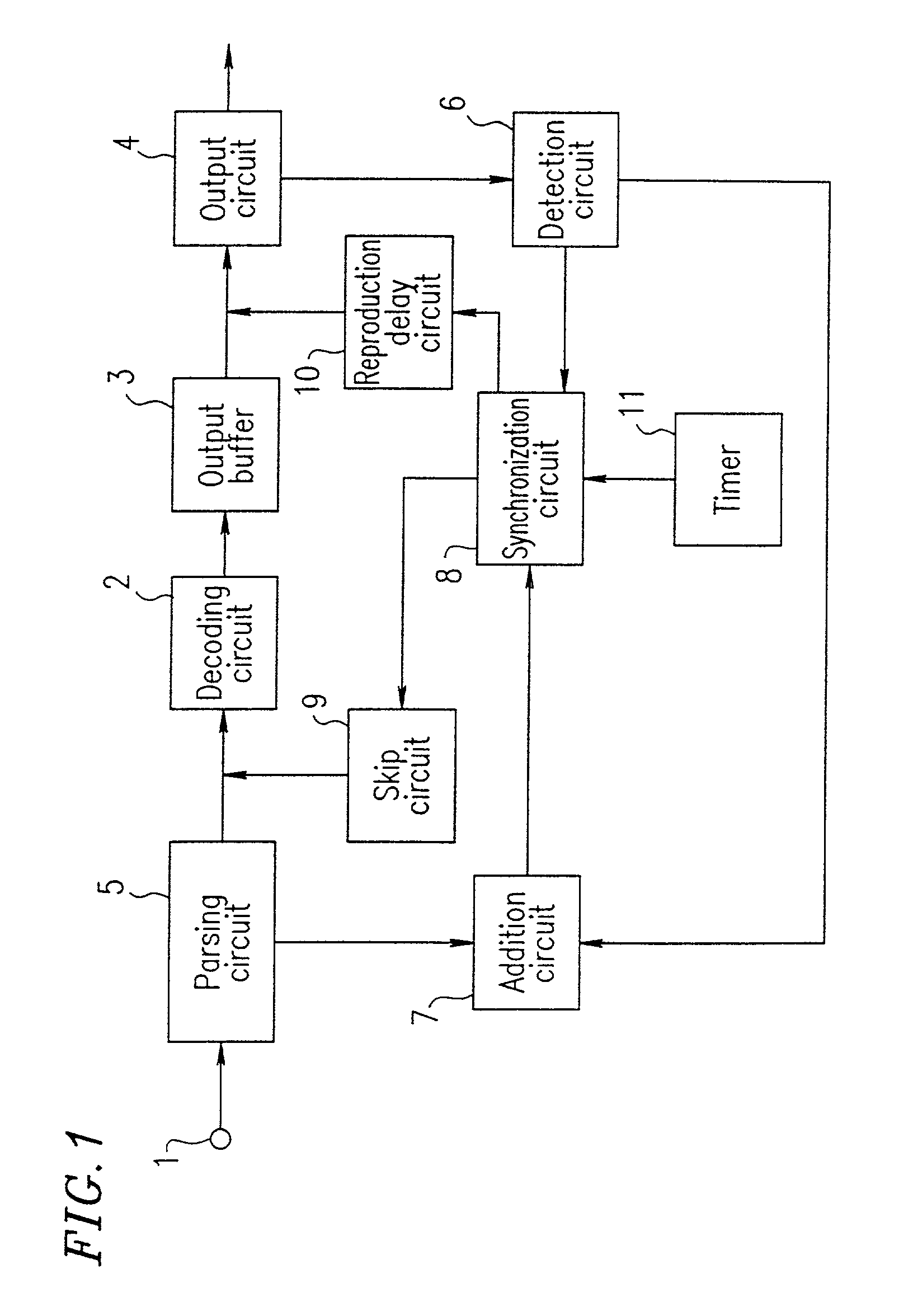
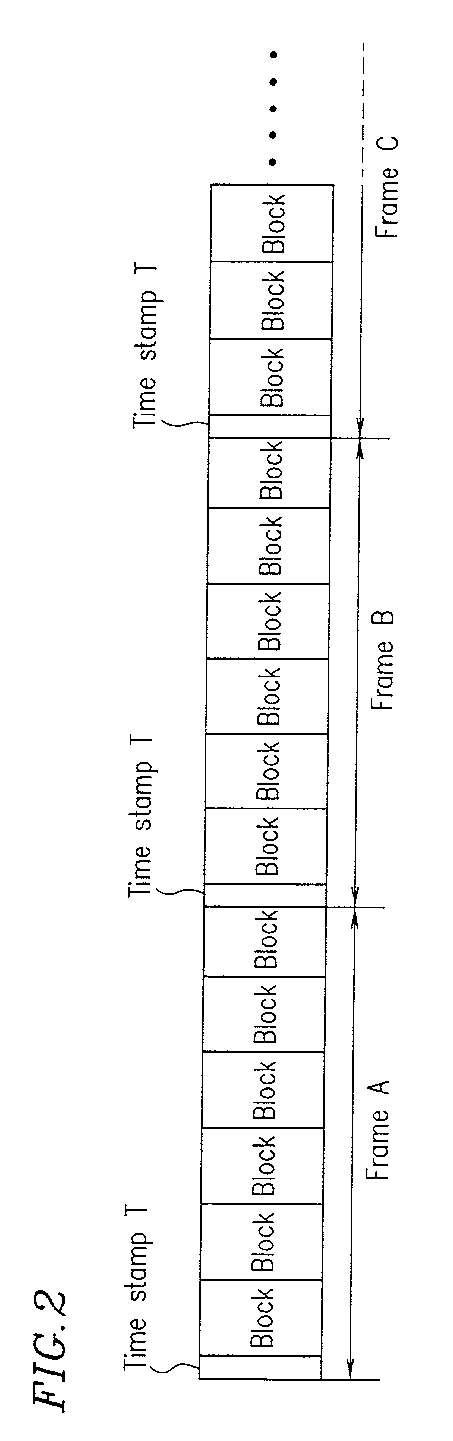
[0102]Hereinafter, Example 1 of the present invention will be described with reference to the accompanying figures. FIG. 1 is a block diagram illustrating a configuration of the compressed code decoding device according to Example 1 of the present invention. FIG. 2 is a diagram illustrating an exemplary configuration of grouped compressed audio codes input to the compressed code decoding device illustrated in FIG. 1.

[0103]As is apparent from FIG. 2, the compressed audio codes are grouped in blocks. The blocks are further grouped in frames, e.g., frames A, B, C, . . . Each frame includes a time stamp T indicating a reproduction time at the beginning of the frame, followed by compressed codes for the frame. The time stamp T indicates a reproduction time when to decode a first block of compressed codes in the frame so as to reproduce audio signals.

[0104]A plurality of frames of compressed codes form a packet, and the compressed codes are transferred by packets. Thus, blocks of compress...

example 2

[0125]Hereinafter, a compressed code decoding device according to Example 2 of the present invention will be described with reference to the accompanying figures. FIG. 3 is a block diagram illustrating a configuration of the compressed code decoding device of Example 2. FIG. 4 is a diagram illustrating an exemplary configuration of grouped compressed audio codes input to the compressed code decoding device illustrated in FIG. 3.

[0126]In the device of the present example, it is assumed that the compressed audio codes and the compressed video codes are transmitted in parallel, as illustrated in FIG. 4, and the respective reproduction times of the frames A, B, C, . . . , of compressed audio codes are synchronized with the respective reproduction times of the frames a, b, c, . . . , of compressed video codes.

[0127]As compared to the device of FIG. 1, the compressed code decoding device illustrated in FIG. 3 is additionally provided with a video parsing circuit 12, a video decoding circu...

example 3

[0138]Hereinafter, a compressed code decoding device according to Example 2 of the present invention will be described with reference to the accompanying figures. FIG. 5 is a block diagram illustrating a configuration of the compressed code decoding device of Example 3. FIG. 6 is a diagram illustrating an exemplary configuration of grouped compressed audio codes input to the compressed code decoding device illustrated in FIG. 5.

[0139]As illustrated in FIG. 6, it is assumed in the present example that a blank period X with no frame exists at predetermined intervals in a series of frames being transmitted. The device of the present example detects the blank period X and reproduces the next frame C after waiting for a length of time corresponding to the blank period X. For example, when compressed audio codes and compressed video codes are transmitted in parallel, since the compressed video codes contain a larger amount of information than the compressed audio codes (and thus the code ...


PUM


Abstract

An audio decoding device is provided for decoding NA (where NA>1) channels of audio signals by a sub-band synthesis operation using sub-band synthesis filter data and sub-band signal data. The decoding device includes a first memory section for storing MA (where MA<NA) channels of the sub-band synthesis filter data and the sub-band signal data, a second memory section for storing at least some of NA channels, an operation section for receiving encoded audio data and decoding the encoded audio data into sub-band signal data, and a data transfer section for, switching, by MA channels, the sub-band synthesis filter data and the sub-band signal data in the first memory section and the second memory section.

Description

[0001]This application is a divisional of U.S. patent application Ser. No. 09 / 080,133 filed on May 15, 1998 now U.S. Pat. No. 6,118,821.BACKGROUND OF THE INVENTION[0002]1. Field of the Invention[0003]The present invention relates to a compressed code decoding device used in AV (audio visual) equipment for decoding and reproducing compressed video signals and audio signals in synchronization with each other. The present invention also relates to an audio signal decoding device for decoding encoded audio data in multiple channels based on a standard such as MPEG 2 so as to obtain a decoded audio signal.[0004]2. Description of the Related Art[0005]In the field of video and audio equipment, CD players and VTRs have become widespread in recent years, and thus there is an increasing demand for large screen display and reproduction of realistic images and sounds for enjoying musics and films at home. In an attempt to satisfy such a demand, media containing video and audio signals have been...

Claims


Application Information

Patent Timeline
IPC IPC(8): G10L19/00G10L21/055H04H20/00H04N7/12H04N7/26H04S3/00
CPCG10L19/00G10L21/055G11B20/10527G11B2020/10787
Inventor MATSUMOTO, MASAHARUKATAYAMA, TAKASHISUEYOSHI, MASAHIROMIYASAKA, SHUJIFUJITA, TAKESHIKAWAMURA, AKIHISAISHITO, TSUKURUOTOMURA, EIJINAKAMURA, TSUYOSHI
Owner PANASONIC CORP
Why Eureka
Try Eureka