Tying device

a technology of tying device and tying rod, which is applied in the direction of fastenings, press-button fasteners, wire tools, etc., can solve the problems of troublesome operation and inconvenient repeated insertion/extraction operation for operators, and achieve the effect of convenient operation and quick winding

Inactive Publication Date: 2006-07-04
RACHET
View PDF6 Cites 17 Cited by
  • Summary
  • Abstract
  • Description
  • Claims
  • Application Information

AI Technical Summary

Benefits of technology

[0005]It is therefore a primary object of the present invention to provide a tying device for tying cargoes. The tying device can be easily operated to quickly winding and tightening a tying belt.

Problems solved by technology

Such repeated insertion / extraction operation is quite inconvenient to an operator.
Such operation is troublesome to the operator.

Method used


Image

  • Tying device
  • Tying device
  • Tying device

Examples


Embodiment Construction

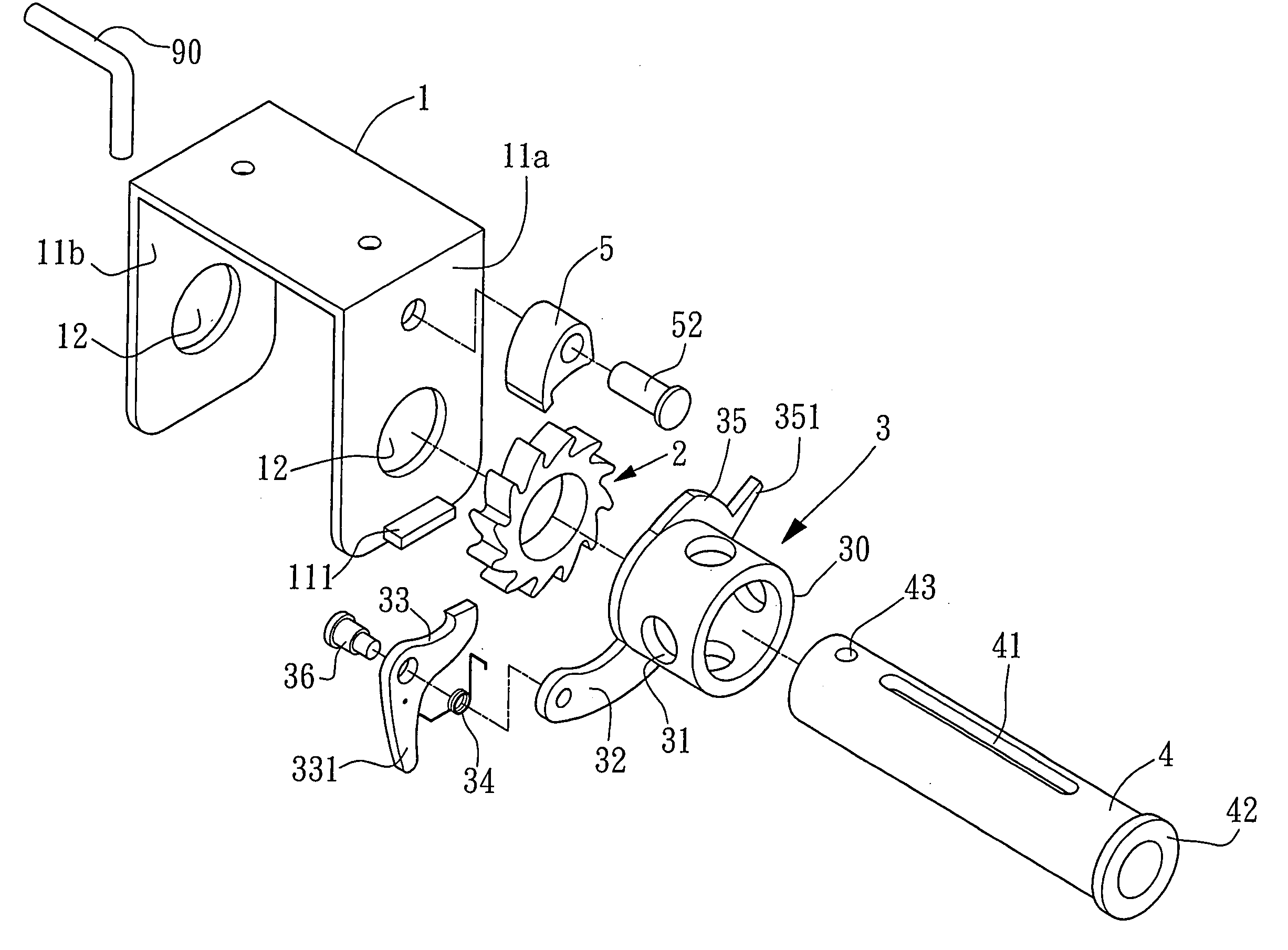
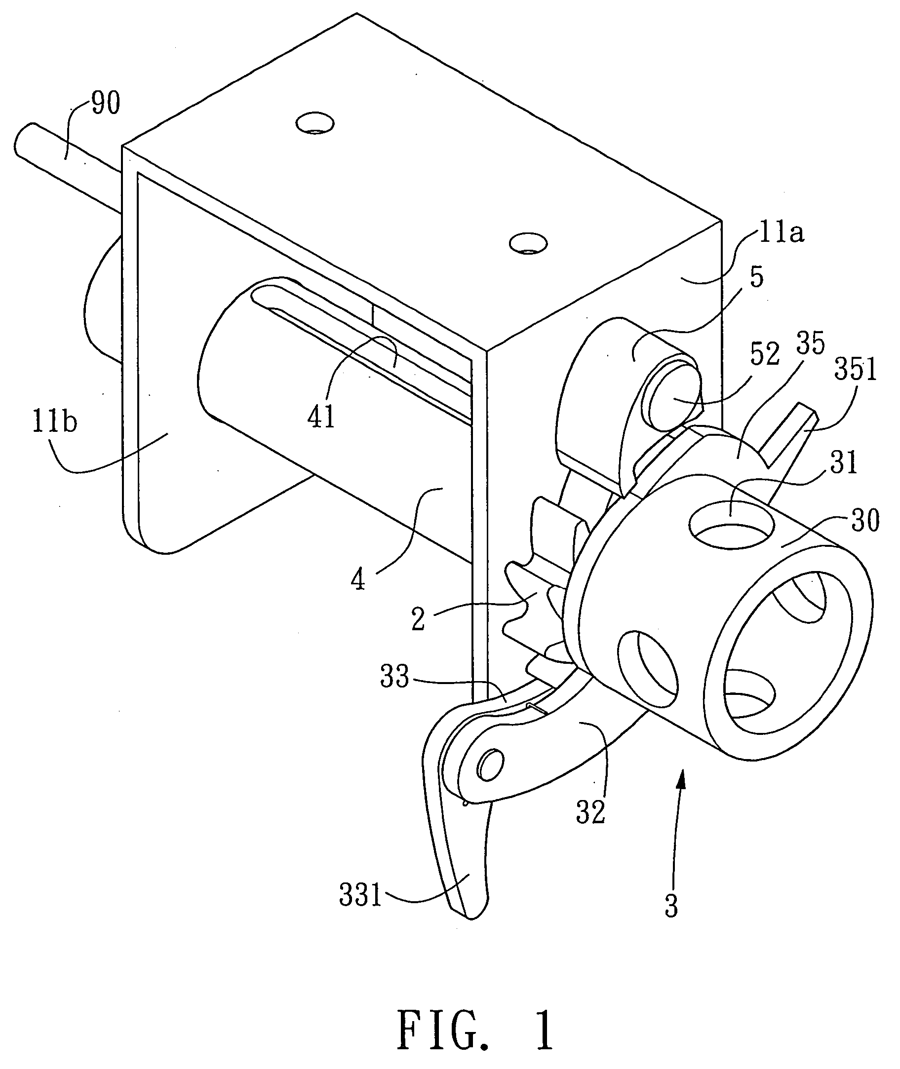
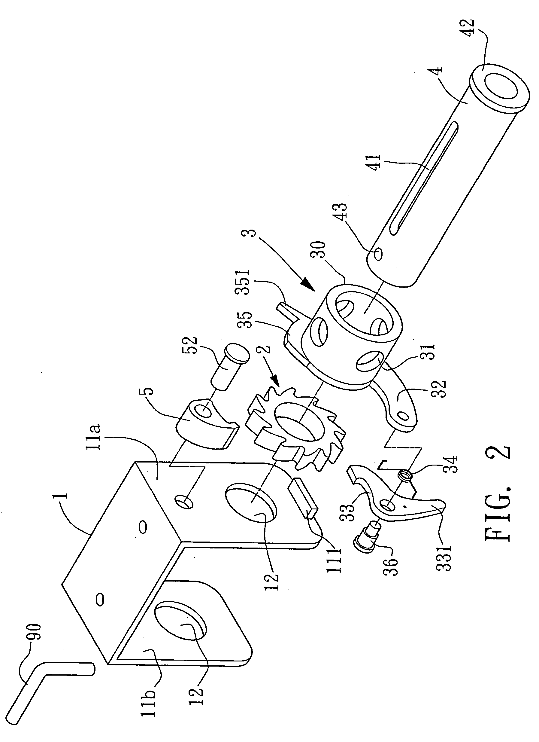
[0026]Please refer to FIGS. 1 to 6. The tying device of the present invention includes a seat body 1, a ratchet wheel 2, a driving member 3, a shaft 4 and a detent member 5.

[0027]The seat body has two opposite sidewalls 11a, 11b each of which is formed with a shaft hole 12 for a shaft 4 to pass therethrough. The shaft 4 is formed with a slot 41 for a tying belt to pass through. A transverse straight stopper section 111 outward projects from bottom end of the sidewall 11a. One end of the shaft 4 is formed with a flange 42 on outer side of the sidewall 11a of the seat body. The driving member 3 is pivotally connected with the end of the shaft 4. The ratchet wheel 2 is fixedly welded on the shaft 4 between the driving member and the sidewall 11a. In this embodiment, the driving member 3 has a cylindrical driving section 30. The circumference of the driving section 30 is formed with several circular holes 31 at intervals. In addition, a rock arm 32 radially outward extends from the circ...


PUM


Abstract

A tying device including a seat body, a ratchet wheel, a driving member, a shaft and a detent member. A shaft is passed through the seat body and connected with the ratchet wheel. The driving member is pivotally connected with the shaft. The driving member can be wrenched to engage the detent member with different ratchets of the ratchet wheel so as to wind or release a tying belt connected with the shaft.

Description

BACKGROUND OF THE INVENTION[0001]The present invention is related to a tying device, and more particularly to a tying device which can be reciprocally driven and conveniently operated for winding and tightening a tying belt.[0002]FIGS. 11 and 12 show a conventional tying device including a seat body 8. Two shaft holes 811 are formed on two sides 81 of the seat body 8 for a shaft 82 to pass therethrough. A driving member 83 is connected with one end of the shaft 82. The circumference of the driving member 83 is formed with several perforations 84 at equal intervals. The body of the shaft 82 is formed with a slot 85 for a tying belt to pass therethrough. After the shaft 82 is extended through the shaft holes 811, the other end of the shaft 82 is pivotally connected with a one-way ratchet 87. A detent block 88 is positioned above the ratchet 87 on outer side of the seat body 8 for dogging the ratchet 87.[0003]In operation of the tying device, as shown in FIGS. 13 and 14, an operating b...

Claims


Application Information

Patent Timeline
Patent Type & Authority Patents(United States)
IPC IPC(8): B25B25/00
CPCB60P7/083Y10T24/2117Y10T24/2175
Inventor LU, JUNG WEN
Owner RACHET
Why Eureka
Try Eureka