Electrical connector assembly with pick up cap

a technology of electric connectors and pick-up caps, which is applied in the direction of electrical apparatus construction details, connection contact material, coupling device connections, etc., can solve the problems of short time needed for curing adhesive films, inability to cure adhesive films uniformly, and inability to ensure uniform curing of adhesive films, etc., to prevent the side effects of contacts and facilitate soldering the connector

Inactive Publication Date: 2006-07-04
HON HAI PRECISION IND CO LTD
View PDF8 Cites 19 Cited by
  • Summary
  • Abstract
  • Description
  • Claims
  • Application Information

AI Technical Summary

Benefits of technology

[0017]An object of the invention is to provide an electrical connector assembly comprising an electrical connector having a number of electrical contacts and a pick up cap, wherein the pick up cap facilitates soldering the connector onto a printed circuit board (PCB) reliably and preventing the contacts from side-effect by outside small dirty material.
[0018]To achieve the above-mentioned object, an electrical connector assembly in accordance with a preferred embodiment of the present invention is provide. The connector assembly comprises a land grid array (LGA) connector and a pick up cap mounted on the connector. The connector defines a number of cells for receiving a corresponding number of contacts. The pick up cap has a planar body forming a plane top surface, which can be sucked by a vacuum suction device to move the connector assembly to a desired location on a PCB, and a bottom surface opposite to the top surface. Several vents are defined in and through the planar body. Each vent extends zigzag from the top surface to the bottom surface, thereby forming an upper chamber and a lower chamber communicating with the upper chamber. The upper chamber displaces with the lower chamber in a manner, such that the upper and lower chambers do not overlap in a direction perpendicular to the top surface to prevent the contacts from any dirty material. During curing adhesive film at high temperature, heated air can flow quickly through the vents and the cells to a bottom portion of the connector and reliable electrical connection between the contacts and the PCB is subsequently produced.

Problems solved by technology

Thus the connector does not have a suitably smooth, integral top surface for engagement by a vacuum suction device.
Generally, the time needed for curing the adhesive film is short.
Thus, the adhesive film is liable to cure non-uniformly.
When this happens, electrical engagement between some of the contacts and the corresponding metal contact pads of the PCB may be flawed.
This increases the time needed for cooling the assembly, which reduces the efficiency of mounting of the connector 8 onto the PCB.
However, a new problem appears because of the vents 60 in the pick up cap 6.

Method used


Image

  • Electrical connector assembly with pick up cap
  • Electrical connector assembly with pick up cap
  • Electrical connector assembly with pick up cap

Examples


Embodiment Construction

[0027]Reference will now be made to the drawings to describe the invention in detail.

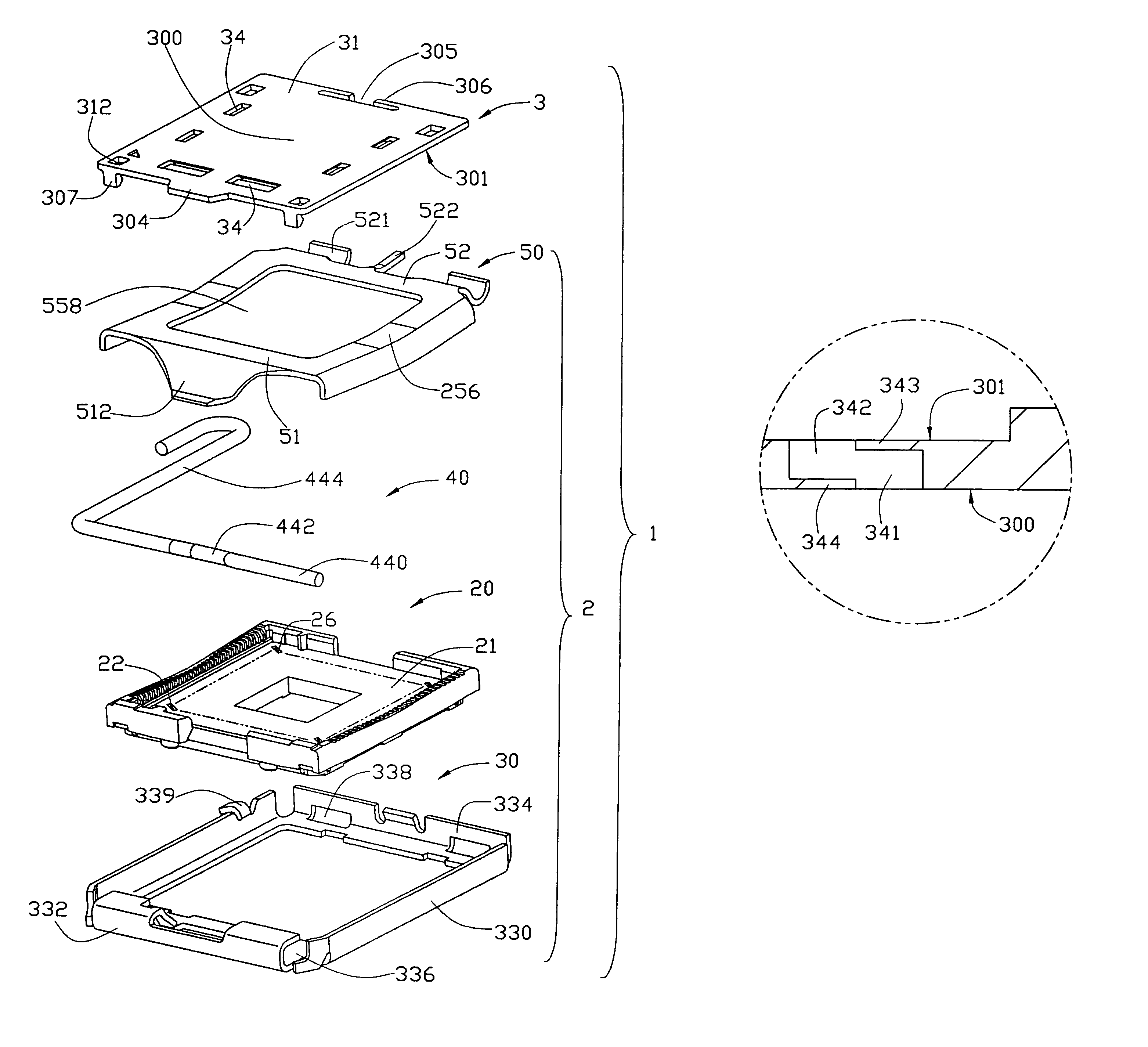
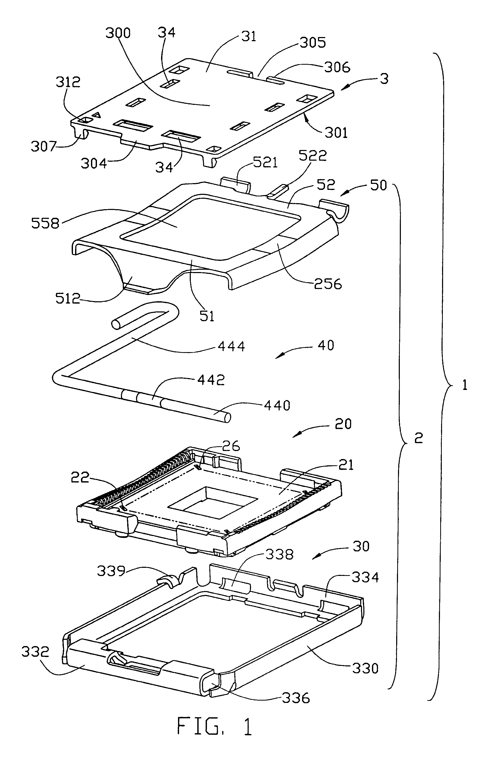
[0028]FIG. 1 is an exploded, isometric view of an electrical connector assembly 1 in accordance with the preferred embodiment of the present invention. The connector assembly 1 comprises a land grid array (LGA) connector 2 and a generally rectangular pick up cap 3. The pick up cap 3 is mounted onto the connector 2, for providing a plane top surface to be engaged by a vacuum suction device (not shown). The connector assembly 1 can thereby be moved onto a circuit substrate, such as a printed circuit board (PCB) (not shown), on which the connector 2 is to be mounted.

[0029]The connector 2 comprises a generally rectangular insulative housing 20, a plurality of electrical contacts 22 received in the housing 20, a frame 30 partly covering and reinforcing the housing 20, an operation member 40 pivotably received in an end of the frame 30, and a load plate 50 pivotably mounted to an opposite end of the frame...


PUM


Abstract

An electrical connector assembly (1) includes an LGA connector (2) and a pick up cap (3) mounted onto the connector. The connector defines a number of cells (26) for receiving a corresponding number of contacts (22). The pick up cap has a planar body (31) forming a plane top surface (300) and a bottom surface (301) opposite to the top surface. Several vents (34) each extend zigzag from the top surface to the bottom surface. Each vent forms an upper chamber (341) and a lower chamber (342) communicating and displacing with each other in a manner, such that the upper and lower chambers do not overlap in a direction perpendicular to the top surface. The vents can prevent the contacts from any dirty material and heated air can flow quickly through the vents and the cells to a bottom portion of the connector during curing adhesive film at high temperature.

Description

BACKGROUND OF THE INVENTION[0001]1. Field of the Invention[0002]The invention is related to an electrical connector assembly which comprised an electrical connector and a pick up cap, the pick up cap being mounted to the connector for providing a flat top surface to be engaged by a vacuum suction device, whereby the connector can be moved onto a circuit substrate such as a printed circuit board (PCB) on which the connector is to be mounted.[0003]2. Description of the Prior Art[0004]At present, on many production lines of the electrical indirty materialry, electronic components such as electrical connectors are mounted onto circuit substrates such as printed circuit boards (PCBs) by surface mount technology (SMT), as disclosed in U.S. Pat. Nos. 5,615,477 and 4,916,805.[0005]A method of mounting an electrical connector onto a PCB by SMT generally comprises a sequence of the following steps A through F:[0006]A—Application of an adhesive film on the PCB having a plurality of metal conta...

Claims


Application Information

Patent Timeline
Patent Type & Authority Patents(United States)
IPC IPC(8): H01R13/44H01R43/02H05K3/30H05K7/10
CPCH05K7/1053H05K3/303
Inventor LIAO, FANG-JWUSZU, MING-LUN
Owner HON HAI PRECISION IND CO LTD
Why Eureka
Try Eureka