
Internal teeth oscillation type inner gearing planetary gear system

a planetary gear system and inner gearing technology, applied in the direction of gearing, gearing elements, hoisting equipment, etc., can solve the problems of difficult to form a large hollow shaft, difficult to secure a large space, and difficult to create a design having a hollow shaft passing through the entire gear system, etc., to achieve smooth power transmission

Inactive Publication Date: 2006-07-04
SUMITOMO HEAVY IND LTD
View PDF11 Cites 10 Cited by
  • Summary
  • Abstract
  • Description
  • Claims
  • Application Information

AI Technical Summary

Benefits of technology

[0016]The present invention is devised to solve this problem. It is an object of the present invention to provide an internal teeth oscillating inner gearing planetary gear system wherein a space for locating piping, wiring, etc. in the central portion of a system can be easily secured according to a particular application, and wherein further smoothness of power transmission can be achieved.
[0018]According to the present invention, the axis of the driving source-end pinion can be offset to a position radially outward of the transmitting external gear. Thus, as a result, the axis of an input shaft (or an output shaft of a driving source) can be removed from the axis of an output shaft. A large diameter hollow shaft can thus be easily formed in an output shaft. Particularly, rotation speed of an inner wall existing in the space formed in the central portion of the gear system can be made very slow. Therefore, a larger space can be secured at lower cost.
[0019]Since all the eccentric shafts can then be “driven equally”, internal teeth oscillating bodies can be oscillatingly driven smoothly in a well-balanced manner.
[0020]Further, it may be more preferable to adopt a structure wherein the transmitting external gear is formed in a ring shape, and is rotatably supported by an outer circumference of any one of the external gear and the output shaft. Thus, even in the instance of a large diameter hollow shaft being formed, the transmitting external gear can be easily incorporated in the system without hindrance.
[0021]In this instance, external teeth of the external gear may be formed by external pins inserted to be freely rotatable in circular grooves thereof, and the external pins may be configured to serve as rollers of bearings of the transmitting external gear. Thereby, reduction of the number of components and shortening of the radial dimension will be made possible.
[0023]Further, according to the present invention, since all the eccentric shafts are equally driven, the eccentric shafts do not necessarily need to be located circumferentially at equal intervals. However, the eccentric shafts may be preferably located circumferentially at equal intervals. Thus, even smoother driving of the internal teeth oscillating bodies will be made possible.

Problems solved by technology

However, with the gear system disclosed in the former patent publication, because of the three eccentric shaft gears i being located circumferentially at equal intervals are driven by the single (pinion 6 of the) input shaft 5, the input shaft is located coaxially with the output shaft, and thus there was difficulty in creating a design having a hollow shaft passing through the entire gear system.
In effect it was nearly impossible to form a large hollow shaft.
In this respect as well it would be difficult to secure a large enough space, and there would also be cost increases.
However, when internal teeth oscillating bodies are driven by a structure wherein the eccentric shafts are located circumferentially at non-equal intervals, a practical problem was encountered in that it was difficult to smoothly oscillate the internal teeth oscillating bodies in a well-balanced manner around the external gear in devices manufactured through a normal manufacturing process.

Method used


Image

  • Internal teeth oscillation type inner gearing planetary gear system
  • Internal teeth oscillation type inner gearing planetary gear system
  • Internal teeth oscillation type inner gearing planetary gear system

Examples


Embodiment Construction

[0032]An embodiment of the present invention will now be described with reference to the drawings.

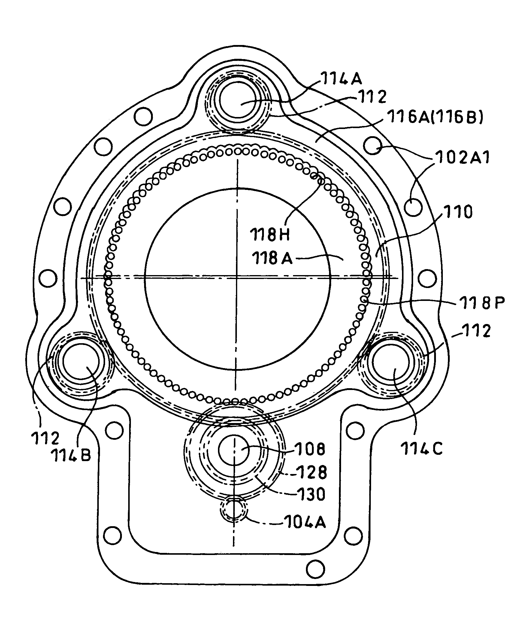
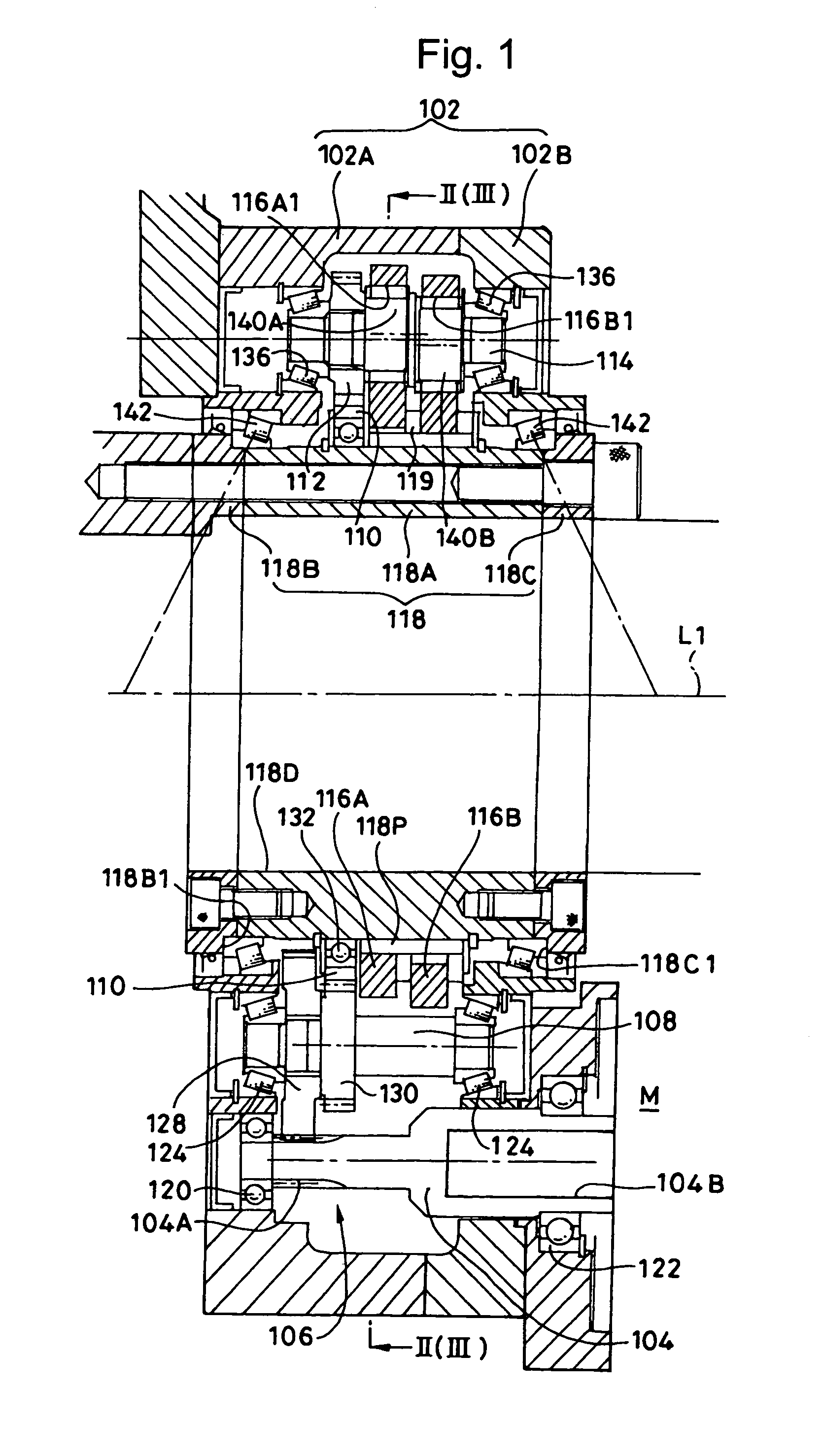
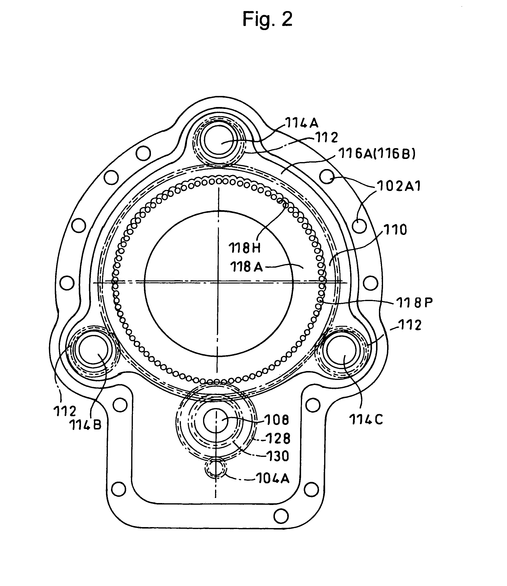
[0033]FIGS. 1 and 2 show an internal teeth oscillating inner gearing planetary gear system (hereafter, simply gear system) 100 according to one embodiment of the present invention. FIG. 1 is a side cross-sectional view of the gear system 100, and FIG. 2 is a cross-sectional view taken along the line II—II in FIG. 1.

[0034]The gear system 100 mainly comprises a main body casing 102, an input shaft 104, a parallel shaft gear set 106, a middle shaft 108, a transmitting external gear 110, eccentric shaft driving gears (eccentric shaft gears) 112, three eccentric shafts 114 (114A through 114C) driven by the eccentric shaft driving gears 112, two internal teeth oscillating bodies (internal gears) 116A and 116B, and an external gear 118 which also functions as an output shaft.

[0035]That is, the gear system 100 comprises the plurality of (three in the embodiment) eccentric shafts 114 passing thr...


PUM


Abstract

An internal teeth oscillating inner gearing planetary gear system, wherein installation space for piping, wiring, etc. can be easily secured in the central portion of the system according to a particular application. The gear system is configured such that rotation of an input shaft is reduced by internal teeth oscillating bodies oscillatingly rotating with respect to an external gear. Eccentric shafts are plurally provided. Eccentric shaft gears are provided for the plurality of eccentric shafts, respectively. A transmitting external gear with which the eccentric shaft gears and a driving source-end pinion concurrently mesh is also provided.

Description

BACKGROUND OF THE INVENTION[0001]1. Field of the Invention[0002]The present invention relates to an internal teeth oscillating inner gearing planetary gear system.[0003]2. Description of the Related Art[0004]Conventional inner gearing planetary gear systems are found widely in various areas where reducers are used, owing to the advantages of large torque transmission capability and large reduction ratios being obtainable.[0005]Among such devices, internal teeth oscillating-type inner gearing planetary gear systems are known wherein rotation of an input shaft is reduced and delivered from an output member through oscillatingly rotating internal teeth oscillating bodies around an external gear, the internal teeth oscillating body having a slight difference in the number of teeth with the external gear (for example, Japanese Patent No. 2607937).[0006]An example of the same gear system will now be explained using FIGS. 4 and 5.[0007]In the drawings, a casing 1 has a first support block ...

Claims


Application Information

Patent Timeline
IPC IPC(8): F16H1/32F16H55/10
CPCF16H1/32F16H2001/323
Inventor TSURUMI, YOHAGA, TAKASHI
Owner SUMITOMO HEAVY IND LTD
Learn More