Vapor deposition apparatus

a technology of vapor deposition apparatus and vapor deposition chamber, which is applied in the direction of separation process, conversion screen, instruments, etc., can solve the problems of difficult to obtain a layer with a constant thickness, the production method cannot be used to produce high-quality screens, and the creation of a lot of expensive residues

Inactive Publication Date: 2006-07-04
T2PHARMA GMBH
View PDF17 Cites 31 Cited by
  • Summary
  • Abstract
  • Description
  • Claims
  • Application Information

AI Technical Summary

Benefits of technology

[0021]The above-mentioned advantageous effects have been advantageously realized by a particular vapor deposition apparatus having the specific features set out in claim 1. Specific features for preferred embodiments of the invention are set out in the dependent claims and in the drawing.

Problems solved by technology

However, this production method can not be used to produce high quality screens with every arbitrary phosphor available.
Moreover, when square or rectangular panels are desired, quite a lot of expensive residue is created while not being deposited onto the plate, rotating with a circular symmetry above the vapor source.
In addition, when depositing material from a fixed source onto such a rotating substrate, it is difficult to obtain a layer with a constant thickness.
This creates a centro-symmetric thickness profile, which means that the thickness of the deposited layer is constant along neither of the sides of a rectangular substrate, unless special precautions are taken, e.g. use of a mask which will however lead to material losses.
In such a batch process a coating failure will generally lead to the complete loss of a panel.
Moreover there will always be a high loss of raw materials in such batch processes.
Lack of deformability of the substrate also limits the format of the coating of a phosphor or scintillator layer on a substrate to the largest cross section of the vacuum deposition chamber.
Besides physical presence of an undesired unevenness at the surface, differences in speed or sensitivity may indeed lay burden on its use as a screen, plate or panel for use in diagnostic imaging, especially when those phosphors are suitable for use in direct radiography as scintillators, in intensifying screens as prompt emitting phosphors or in storage panels as stimulable phosphors, used in computed radiography (CR).

Method used


Image

  • Vapor deposition apparatus
  • Vapor deposition apparatus
  • Vapor deposition apparatus

Examples


example 1

[0086]A CsBr:Eu photostimulable phosphor screen having a flexible anodized aluminum was prepared in a vacuum chamber by means of a thermal vapor deposition process, starting from a mixture of CsBr and EuOBr as raw materials. Said deposition process onto said flexible anodized aluminum support was performed in such a way that said support was moving so that the momentary magnitude of the velocity was constant over its whole area.

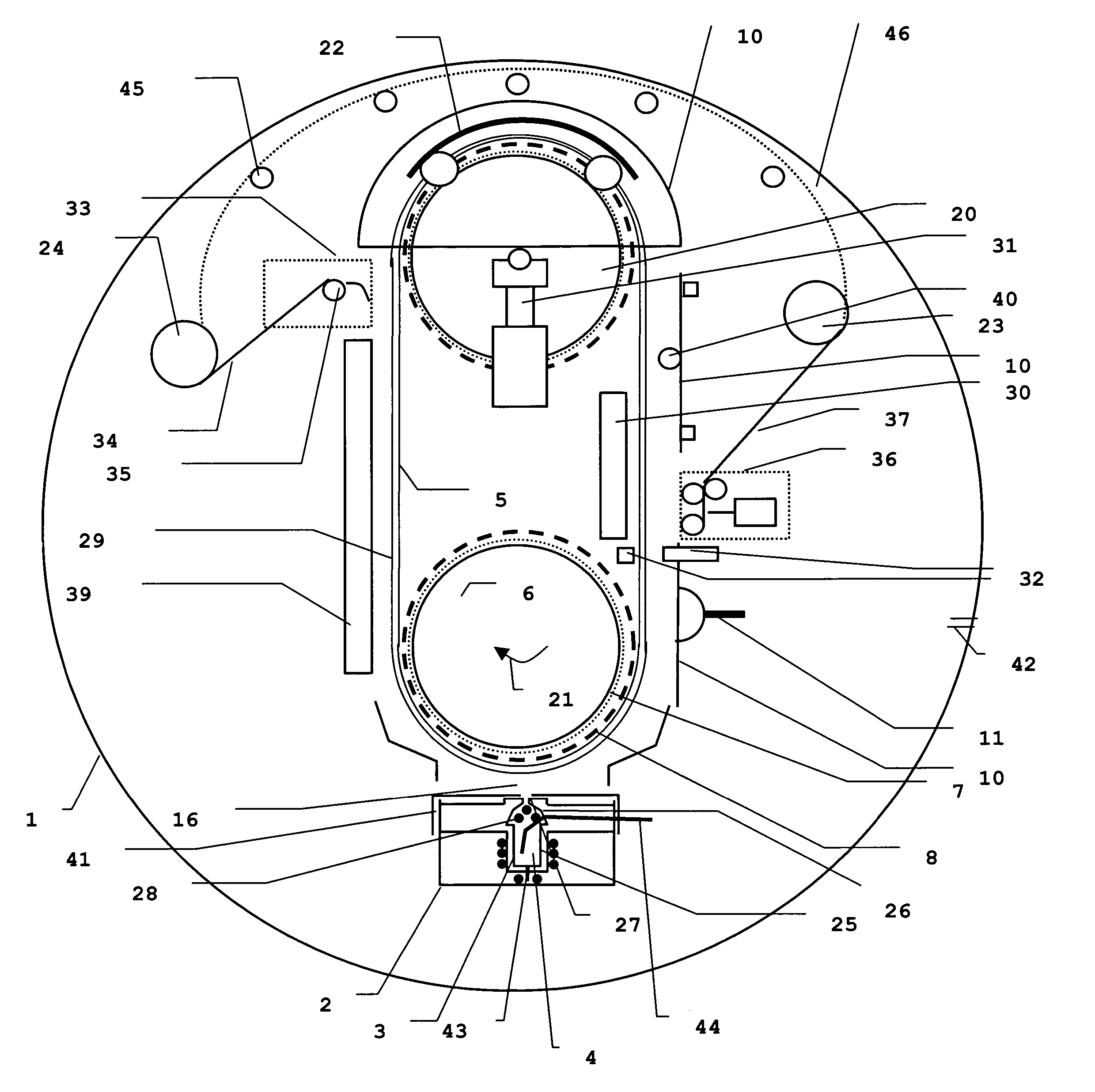
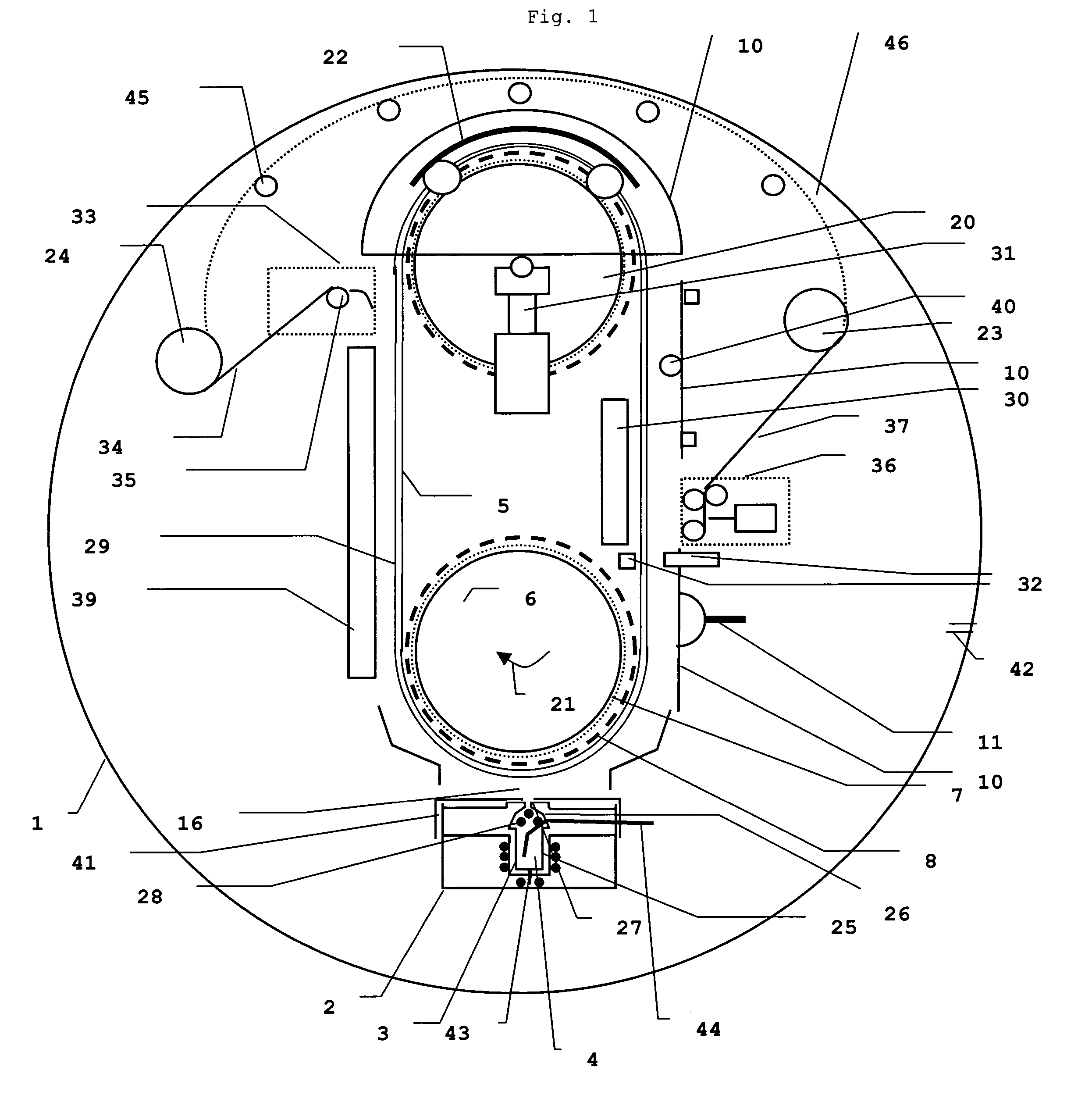
[0087]Referring to FIG. 2 the cylindrical vacuum chamber (1) with a diameter of 1.4 m and a length of 1.75 m was containing an electrically heated oven (2) and a refractory tray or boat (3) in which 4 kg of a mixture (4) of CsBr and EuOBr as raw materials in a 99.5% / 0.5% CsBr / EuOBr percentage ratio by weight were present to become vaporized.

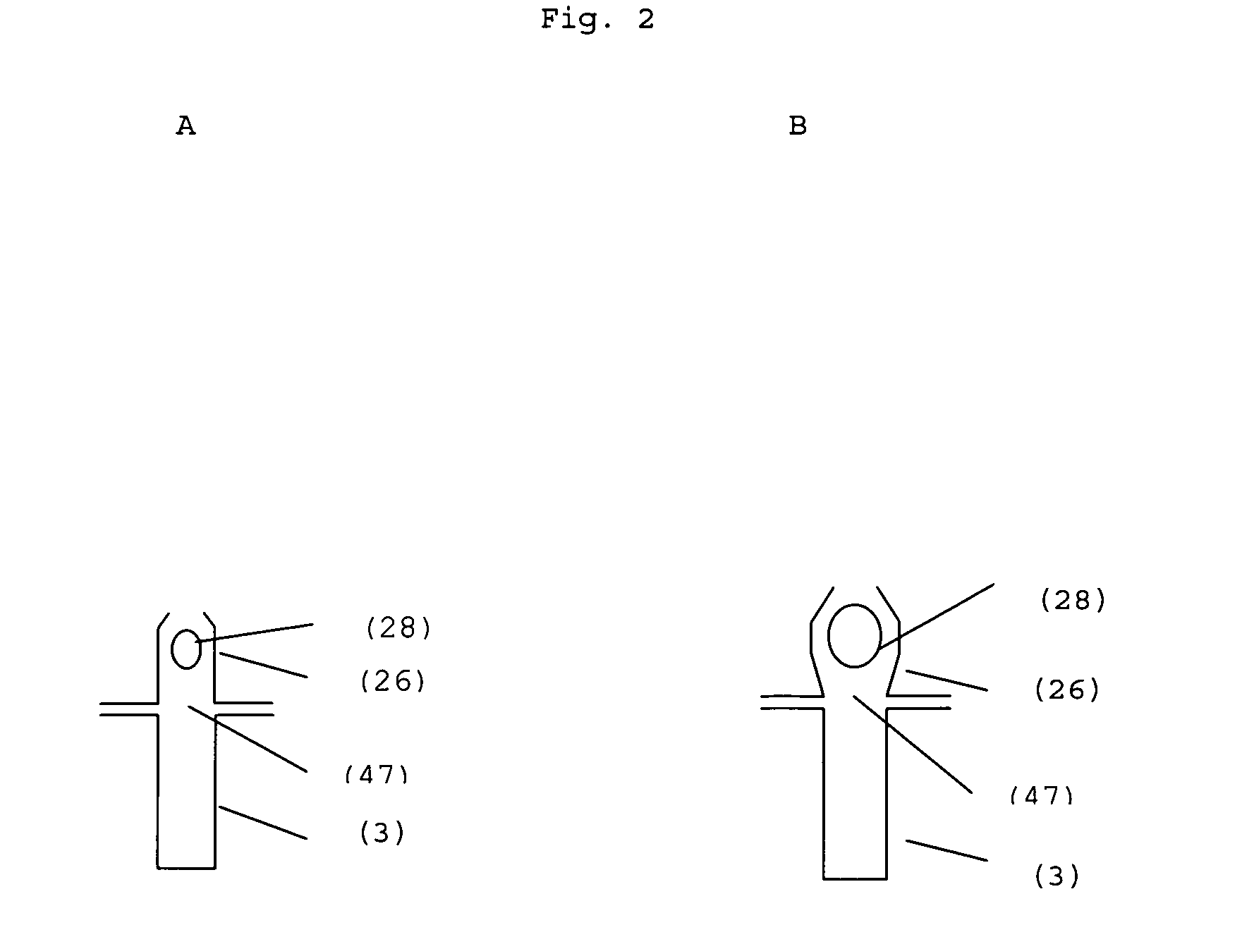
[0088]Crucible (3) was an elongated boat having a length of 1 m and a width of 4 cm composed of “tantalum” having a thickness of 0.5 mm, composed of 3 integrated parts: a crucible container (25), an internally heated chimn...


PUM

PropertyMeasurementUnit
thicknessaaaaaaaaaa
thicknessaaaaaaaaaa
thicknessaaaaaaaaaa

Abstract

A vapor deposition apparatus, developed in particular for on-line deposition of phosphor or scintillator material, wherein said vapor deposition apparatus comprises a crucible containing a mixture of raw materials, a chimney having at least one inlet in communication with the said crucible and a linear slot outlet, one or more lineair heating elements, contained within said chimney, an oven surrounding said crucible, wherein said oven contains heating elements, shielding elements and cooling elements.

Description

FIELD OF THE INVENTION[0001]The present invention relates to a vapor deposition apparatus, developed in particular for on-line deposition of phosphor or scintillator material in the manufacturing or production of scintillator or phosphor sheets, used in screens, panels or plates suitable for use in high energy radiation detection and imaging and, more particularly, in computed radiography, screen / film radiography and is direct radiography.BACKGROUND OF THE INVENTION[0002]In radiography the interior of objects is reproduced by means of penetrating radiation, which is high energy radiation also known as ionizing radiation belonging to the class of X-rays, γ-rays and high-energy elementary particle rays, e.g. β-rays, electron beam or neutron radiation.[0003]For the conversion of penetrating radiation into visible light and / or ultraviolet radiation “luminescent” substances, called “phosphors”, are used. Cathodoluminescent phosphors employed e.g. in CRT screens exhibit two related lumine...

Claims


Application Information

Patent Timeline
Patent Type & Authority Patents(United States)
IPC IPC(8): C23C14/24C09K11/08G21K4/00C23C14/06C23C14/50C23C14/54G01T1/20
CPCC09K11/08C23C14/0694C23C14/541C23C14/505C23C14/243
Inventor GUIDO, VERREYKENPETER, BLUYSRUDY, HENDRICKXLUCAS, PEETERSJOHAN, LAMOTTE
Owner T2PHARMA GMBH
Why Eureka
Try Eureka