Method of non-contact measuring electrical conductivity of electrolytes with using primary measuring transformer

a technology of electrical conductivity and non-contact measurement, applied in the direction of fluid resistance measurement, instruments, material impedance, etc., can solve the problems of polarization not always reversible, electrode symmetry disturbance, and state may not be restored

Inactive Publication Date: 2006-07-04
ENERIZE CORP
View PDF8 Cites 7 Cited by
  • Summary
  • Abstract
  • Description
  • Claims
  • Application Information

AI Technical Summary

Problems solved by technology

This will result in a disturbance of the electrodes symmetry: one of them will be coated with a copper layer while the other will have a film of oxygen.
Such polarization is not always reversible: after the discharge of the element the initial state may not be restored.
The generation of the polarization e.m.f. creates a number of serious problems.
But work A′ is unavoidable, and its value is a function of the electrolyte composition and the material of the electrodes.
Among the disadvantages of the method for electrolyte conductivity measuring by using contact electrodes and the alternating current is the following.
Nevertheless this condition is not enough to guarantee the measurement reliability.
A common disadvantage of these patents is that the measurements are performed at one fixed frequency, without considering the issues related to the frequency dispersion of the specific electrical conductance of liquid electrolytes.
A disadvantage is that the proposed solutions do not allow determining the frequency characteristics of the process of charges transfer in the electrolyte.
A disadvantage of the patent is the impossibility of studying conductivity within the frequency range.
Such a deposit introduces a serious error into the results of measuring the electrical conductivity of a liquid electrolyte.
The disadvantages of this method are absence of means for measuring the frequency dependence of the electrolyte conductivity, and also the fact that the flexible membrane forms an intricate surface configuration of the liquid relative to the pickup inductance coil of the sensor.

Method used


Image

  • Method of non-contact measuring electrical conductivity of electrolytes with using primary measuring transformer
  • Method of non-contact measuring electrical conductivity of electrolytes with using primary measuring transformer
  • Method of non-contact measuring electrical conductivity of electrolytes with using primary measuring transformer

Examples


example 1

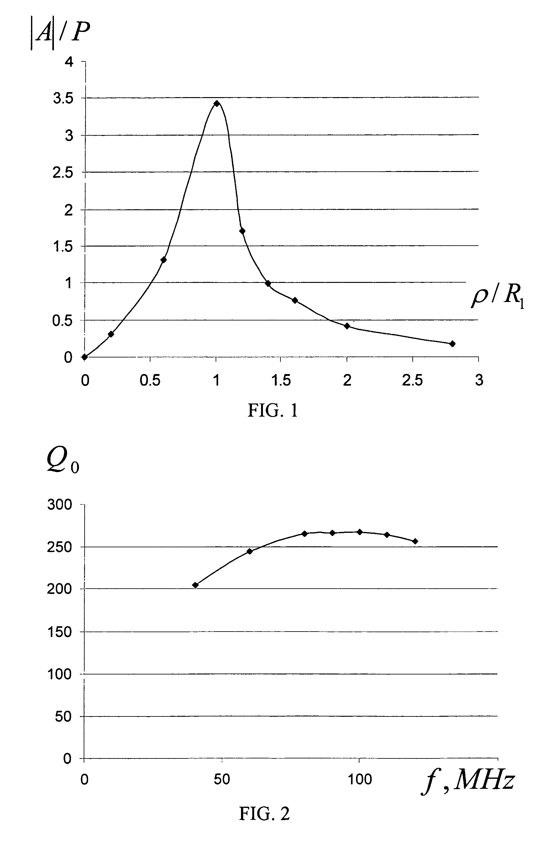
[0107]The example illustrates the methodology of selecting the first operating frequency.

[0108]The relationship between the own Q-factor of the eddy current sensor Q0=ωL0 / r and the frequency has an extremal character. The explanation is that with the increase of the frequency the Q-factor is initially predominantly influenced by the growth of the inductance resistance that is found in the numerator. In this case Q0 is increased. Then starts prevailing the increase of the active resistance of the winding wire due to the current expulsion into the surface layer of the wire that has a higher resistance (skin effect).The extremum value and position depend on the geometry of the eddy current sensor, its dimensions, number of turns, availability and properties of the core, surface condition of the winding wire.

[0109]FIG. 2 shows the frequency characteristic of the own Q-factor of the eddy current sensor having the following parameters: sensor turn diameter Dav=14.5 mm, number of turns W=3...

example 2

[0111]From the expression for the generalized parameter β (4) (β=R1√{square root over (ωσμ0)}, where R1 is the radius of the eddy current sensor, ω—field frequency, σ—specific electrical conductance), that determines at the fixed clearance and sample thickness the introduced impedance of the eddy current sensor, it follows that frequency ω influences the value of the relative introduced active resistance Rυ / ωL0=Rv′ in the same degree as the squared radius of the sensor. Let us check how this theoretical statement is valid for materials with low σ.

[0112]The studies were performed on the test samples whose conductance depends on the movement of free charges, electrons and holes. Alloyed monocrystals of germanium and silicon semiconductors were used as electrical conductance test samples. The ohmic character of the conductance of the monocrystals, rather high homogeneity (electrical conductance variation values of the test samples after selection did not exceed 0.5%), absence of freque...

example 3

[0117]This is an example of studying the influence of reducing the number of turns on the introduced resistances Rv1 / ω1L0 and Rv2 / qω2L0.

[0118]Let us study the changes of the relative introduced active resistance of an eddy current sensor in the form of a short cylindrical inductance coil that occur with the reduction of the number of turns W. FIG. 5 shows the relationships between the relative introduced active resistance Rv / ωL0=Rv of the cylindrically shaped eddy current transducer of diameter D=14.7 mm and the number of turns W closely wound with a 0.4 mm diameter wire, the sensor's magnetic field frequency is f=19.5 MHz. The relationships were obtained on the germanium and silicon monocrystal samples with conductance values σ=1.2; 17.9; 200; Cm / m. An interesting feature of these characteristics is the presence of the maximum. This maximum with the increase of the total parameter β=R1√{square root over (ωσμ0)} becomes more vividly expressed and shifts to the field of lower values ...


PUM

PropertyMeasurementUnit
diameteraaaaaaaaaa
thickaaaaaaaaaa
diametersaaaaaaaaaa

Abstract

A method of noncontact measuring the electrical conductivity of electrolytes using a primary measuring transformer includes placing the electrolyte in a sampler, exciting an alternating magnetic field using an axisymmetrical eddy current sensor, switching to the sensor a capacitor of variable capacitance, tuning of the formed circuit in resonance with the frequency of the generator of harmonic oscillations, and recording the change in the introduced active resistance of the parametric eddy current sensor rated against its own inductive resistance.

Description

CROSS-REFERENCE TO RELATED APPLICATIONS[0001]This application claims the benefit of Ukraine Patent Application No. 2003007005, filed Jul. 25, 2003; and Ukraine Patent No. 60954A, filed Oct. 15, 2003, which are incorporated herein by reference.STATEMENT REGARDING FEDERALLY SPONSORED RESEARCH OR DEVELOPMENT[0002]Not applicable.FIELD OF THE INVENTION[0003]The invention relates to electrical engineering industry, in particular to the field of measuring electrical properties of electrolytes used in chemical power sources, and refers to a method and a primary measuring transducer for measuring their electrical conductivity.BACKGROUND OF THE INVENTION[0004]The electrical conductivity of electrolytes in the majority of cases has been traditionally measured using a contact method. In such case the trustworthiness of the obtained results is greatly influenced by the contact phenomena. Let us discuss it on the basis of an example.[0005]Let us assume that two identical metallic electrodes, for ...

Claims


Application Information

Patent Timeline
Patent Type & Authority Patents(United States)
IPC IPC(8): G01R27/00G01N27/00G01N27/72G01R33/20G01R33/30G01N27/02G01N27/06G01N27/07G01R27/22
CPCG01N27/023G01N27/07G01N27/06G01R27/22
Inventor RED'KO, VOLODYMYRKHANDETSKYY, VOLODYMYRSHEMBEL, ELENANOVAK, PETER
Owner ENERIZE CORP
Why Eureka
Try Eureka