Optical scanning apparatus, multi-beam optical scanning apparatus, and image-forming apparatus

a scanning apparatus and optical scanning technology, applied in the field of optical scanning apparatus and multi-beam optical scanning apparatus, can solve the problems of increased sub-scanning magnification, irregular pitch, and variable siz

Inactive Publication Date: 2006-07-04
CANON KK
View PDF16 Cites 4 Cited by
  • Summary
  • Abstract
  • Description
  • Claims
  • Application Information

AI Technical Summary

Problems solved by technology

There was, however, the problem that nonuniformity of lateral magnification (which will also be referred to hereinafter as “sub-scanning magnification”) in the sub-scanning direction appeared prominent at wide angles of view and even if the image positions in the sub-scanning direction were corrected the spot size would vary in proportion to sub-scanning magnifications at respective scanning positions.
Further, in the case of the optical scanning apparatus using multiple beams, they suffered from the problem that with deviation of the sub-scanning magnifications from a fixed value, line pitch intervals in the sub-scanning direction varied at every scanning position on the surface to be scanned during the optical scanning of that surface, so as to result in irregular pitch.
However, there was the problem that it increased the sub-scanning magnification and the asymmetry of the image positions in the sub-scanning direction and the asymmetry of the sub-scanning magnifications appeared more prominent.

Method used


Image

  • Optical scanning apparatus, multi-beam optical scanning apparatus, and image-forming apparatus
  • Optical scanning apparatus, multi-beam optical scanning apparatus, and image-forming apparatus
  • Optical scanning apparatus, multi-beam optical scanning apparatus, and image-forming apparatus

Examples


embodiment 1

[Embodiment 1]

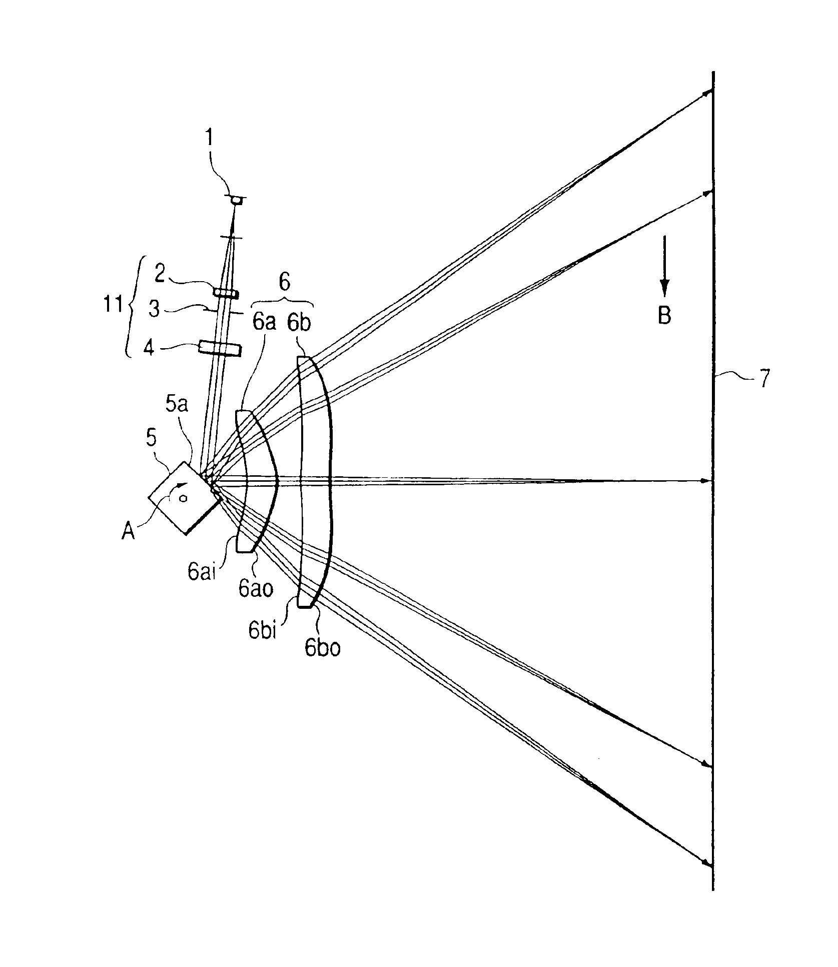
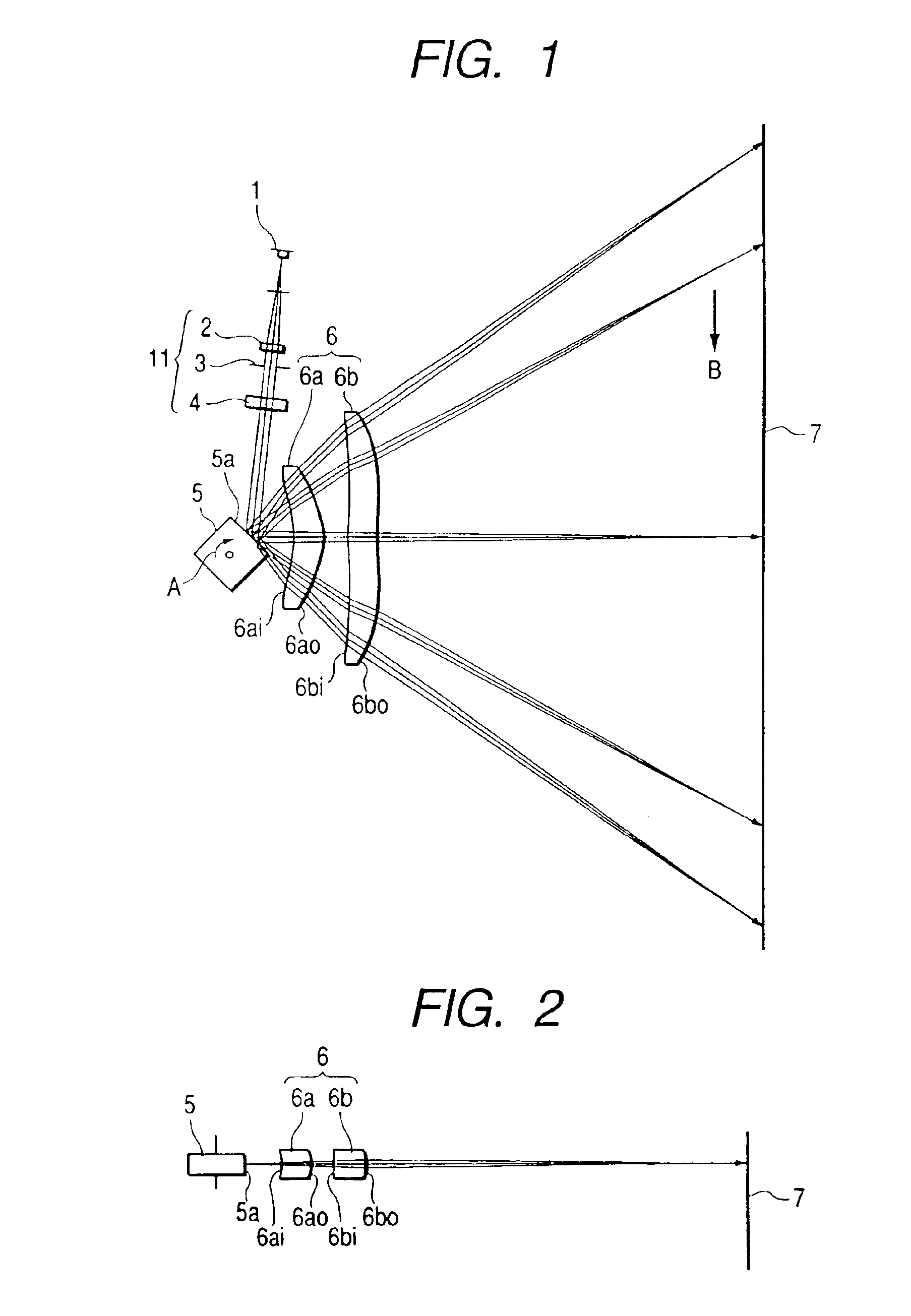
[0051]FIG. 1 is a cross-sectional view of the principal part along the main scanning direction (a main scanning section) of the optical scanning apparatus in Embodiment 1 of the present invention and FIG. 2 is a cross-sectional view of the principal part along the sub-scanning direction (a sub-scanning section) of FIG. 1.

[0052]In the present specification the main scanning direction (meridional direction) is defined along the direction into which the light is reflectively deflected (or deflected to scan) by the deflecting means, and the sub-scanning direction (sagittal direction) along the direction perpendicular to the optical axis of the scanning optical means and to the main scanning direction.

[0053]In the figures, numeral 1 designates a light source means, which is comprised, for example, of a semiconductor laser. Numeral 2 denotes a collimator lens (condenser lens), which converts a diverging beam (light beam) emitted from the light source means 1 into a nearly pa...

embodiment 2

[Embodiment 2]

[0078]Described next is the multi-beam optical scanning apparatus in Embodiment 2 of the present invention.

[0079]The present embodiment is different from above Embodiment 1 in that the light source means 1 is comprised of a multi beam semiconductor laser consisting of two light-emitting regions and in that degrees of change are different for the curvatures in the sagittal direction in the surfaces of the first and second fθ lenses 6a, 6b constituting the scanning optical means 6. The other structure and optical action are substantially the same as in Embodiment 1, thereby achieving like effect.

[0080]The optical layout of the scanning optical means 6 and the aspherical coefficients of the first and second fθ lenses 6a, 6b in the present embodiment are presented in Table 3 and Table 4, respectively. FIG. 7 and FIG. 8 are diagrams to show how the curvatures in the sagittal direction change in each of the surfaces of the first and second fθ lenses 6a, 6b, respectively, in ...

embodiment 3

[Embodiment 3]

[0096]Described next is the multi-beam optical scanning apparatus in Embodiment 3 of the present invention.

[0097]The present embodiment is different from above Embodiment 2 in that all the lens surfaces of the first and second fθ lenses 6a, 6b constituting the scanning optical means 6 are formed in the concave shape opposed to the optical deflector 5 and in that degrees of change in the curvatures in the sagittal direction are different. The other structure and optical action are substantially the same as in Embodiment 2, thereby achieving like effect.

[0098]The optical layout of the scanning optical means 6 and the aspherical coefficients of the first and second fθ lenses 6a, 6b in the present embodiment are presented in Table 5 and Table 6, respectively. FIG. 10 and FIG. 11 are diagrams to show how the curvatures in the sagittal direction change in each of the surfaces of the first and second fθ lenses 6a, 6b, respectively, in the present embodiment.

[0099]

TABLE 5LAYOU...


PUM


Abstract

Provided are compact, high-definition, optical scanning apparatus and multi-beam scanning apparatus capable of keeping the spot size uniform in the sub-scanning direction throughout the entire, effective scanning area on a surface to be scanned. An optical scanning apparatus has an entrance optical system 11 for guiding light emitted from a light source 1, to a deflector 5, and a scanning optical system 6 for focusing the light reflectively deflected by the deflector, on a surface to be scanned 7. In the optical scanning apparatus, the scanning optical system has a plurality of sagittal asymmetric change surfaces in which curvatures in the sagittal direction change on an asymmetric basis in the meridional direction with respect to the optical axis of the scanning optical system.

Description

[0001]This is a divisional application of application Ser. No. 09 / 696,000, filed Oct. 26, 2000, U.S. Pat No. 6,943,927.BACKGROUND OF THE INVENTION[0002]1. Field of the Invention[0003]The present invention relates to optical scanning apparatus and multi-beam optical scanning apparatus and, particularly, the invention is suitably applicable to image-forming apparatus, for example, such as laser beam printers involving the electrophotographic process, digital copiers, and the like, constructed so as to record image information by reflectively deflecting light from light source means by deflecting means to optically scan a surface to be scanned, via scanning optical means with the light.[0004]2. Related Background Art[0005]In the optical scanning apparatus such as the laser beam printers, the digital copiers, etc. heretofore, the image information was recorded in such a manner that the light optically modulated according to an image signal and outputted from the light source means was p...

Claims


Application Information

Patent Timeline
Patent Type & Authority Patents(United States)
IPC IPC(8): G02B26/08B41J2/44G02B13/00G02B13/18G02B26/10G02B26/12H04N1/113
CPCB41J2/473G02B26/125G02B26/123H04N1/1135G02B26/10
Inventor ISHIHARA, KEIICHIRO
Owner CANON KK
Why Eureka
Try Eureka