Refuse vehicle control system and method

a vehicle control and vehicle technology, applied in the field of vehicle recycling, can solve the problems of increasing repair and maintenance costs, reducing the operative life of the front loader, and causing unnecessary wear and tear on the front loader

Inactive Publication Date: 2006-07-04
OSHKOSH CORPORATION
View PDF135 Cites 113 Cited by
  • Summary
  • Abstract
  • Description
  • Claims
  • Application Information

AI Technical Summary

Problems solved by technology

Unfortunately, this process has a number of disadvantages.
Unfortunately, these repetitive movements may result in the arms and forks reaching their mechanical stops causing undue wear and tear on the front loader.
This wear and tear may decrease the operative life of the front loader and result in increased repair and maintenance costs.
In other situations, refuse vehicles having front loaders may spill refuse on the ground as the refuse bin is being lifted.
This is often a problem when the refuse bin has been overfilled.
During this transition, refuse may be spilled.
This process results in a significant loss of efficiency for the operator of the refuse vehicle.
In addition to the efficiency loss, some of the spilled refuse may be blown away or scattered such that it would take too much of the operator's time to put it back in the refuse bin.
The result may be refuse distributed near and around the location of a refuse bin.
This is very undesirable aesthetically and may have significant negative environmental impacts on the surrounding area.
Further, in other situations, the operator of the refuse vehicle may have difficulty determining the location of the arms and forks.
This may especially be a problem when the arms and forks are located above the cab of the refuse vehicle and out of sight of the operator.
Unfortunately, the operator is typically limited to visually verifying the position of the arms and forks.
In other situations, the operator may not be aware of the position of the various components of the refuse vehicle and attempt to perform a function that may result in damaging the refuse vehicle or spilling refuse.
Such a mistake may result in spilled refuse distributed on the vehicle and the adjacent ground.
In this situation, the refuse would be pressed up against the tailgate by the packer with tremendous force.
This may result in significant and costly damage to the refuse vehicle.

Method used


Image

  • Refuse vehicle control system and method
  • Refuse vehicle control system and method
  • Refuse vehicle control system and method

Examples


Embodiment Construction

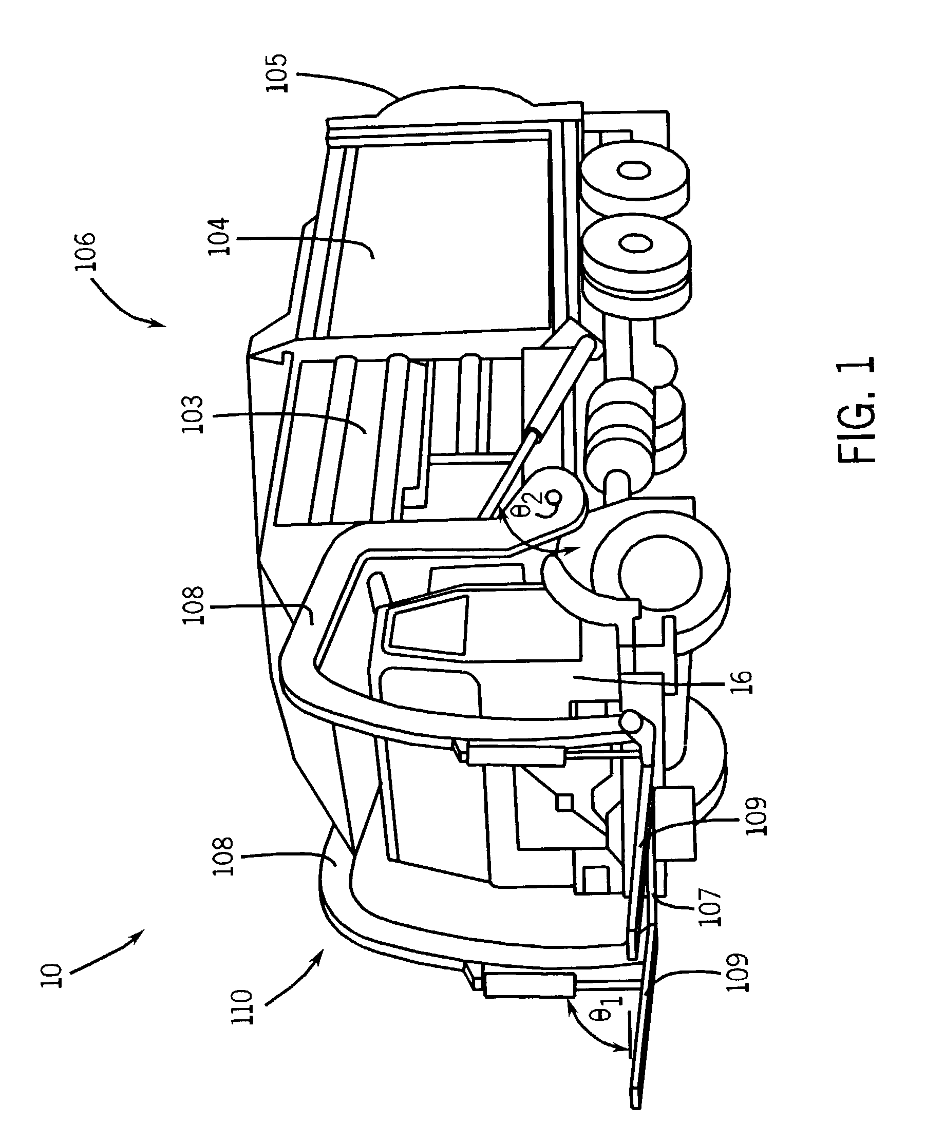
[0023]Referring to FIG. 1, one embodiment of a refuse vehicle 10 is illustrated. By way of overview, the refuse vehicle 10 generally includes a chassis and a vehicle body mounted on the chassis, with the chassis and the vehicle body in combination including an operator compartment 16 capable of receiving a human operator. The operator compartment 16 further includes steering and throttle controls for receiving operator inputs to control the movement of the refuse vehicle 10 along a road. A refuse loader 110 may be mounted to refuse vehicle 10, and can be configured to move a load of refuse along a path and into the refuse vehicle 10.

[0024]It should be understood that FIG. 1 merely illustrates one embodiment, and the refuse vehicle 10 may include a variety of configurations. For example, in FIG. 1, the refuse vehicle 10 includes a front loading refuse loader. However, it should be understood that the applicability of the present disclosure is not limited to front loading refuse vehic...


PUM


Abstract

A refuse vehicle is disclosed comprising a refuse loader capable of moving a load of refuse along a path and into the refuse vehicle and an electronic control system capable of controlling the refuse loader. The refuse loader controlled by the electronic control system is capable of moving the load along the path and performing an operation in relation to a position along the path.

Description

CROSS-REFERENCE TO RELATED PATENT APPLICATIONS[0001]This application is a continuation-in-part of U.S. Ser. No. 09 / 927,946, filed Aug. 10, 2001, pending, which is a continuation-in-part of U.S. Ser. No. 09 / 384,393, filed Aug. 27, 1999, now U.S. Pat. No. 6,421,593, which is a continuation-in-part of U.S. Ser. No. 09 / 364,690, filed Jul. 30, 1999, abandoned, each of which is hereby expressly incorporated by reference. This application also claims priority to U.S. Prov. No. 60 / 342,292, filed Dec. 21, 2001, also hereby expressly incorporated by reference.FIELD OF THE INVENTION[0002]The present invention relates generally to the field of refuse vehicles. More specifically, the present invention relates to refuse vehicle control systems for refuse vehicles.BACKGROUND OF THE INVENTION[0003]Various vehicles are known for use in collecting and transporting refuse. Refuse vehicles often employ a refuse loader to load refuse into the refuse vehicle's refuse container. One example of such a refu...

Claims


Application Information

Patent Timeline
Patent Type & Authority Patents(United States)
IPC IPC(8): G05D1/00B62D33/06B65B21/02A62C27/00B60L3/12B60L50/15B60R16/02B60R16/03B65F3/02B65F3/04G05B19/00G05B19/4097G07C5/08G08G1/123
CPCB60L11/12B60R16/0315B65F3/043B65F3/045B65F3/046G05B19/00G05B19/4097G07C5/08G08G1/20B60L3/12A62C27/00Y02T10/7077B65F2003/0256B65F2003/0279G07C5/008Y02W30/10B60L50/15Y02T10/7072
Inventor PILLAR, DUANE R.DANTZMAN, GREGORY P.BICE, RANDALL L.WOOLMAN, WILLIAM M.
Owner OSHKOSH CORPORATION
Why Eureka
Try Eureka