
Extended storage capacity for a network file server

a file server and network file technology, applied in the field of storage networks, can solve the problems of no centralized control, more expensive and powerful san (storage area network) file server use, and the disadvantages of nas storage networks over san storage networks

Active Publication Date: 2006-07-04
CISCO TECH INC
View PDF13 Cites 146 Cited by
  • Summary
  • Abstract
  • Description
  • Claims
  • Application Information

AI Technical Summary

Benefits of technology

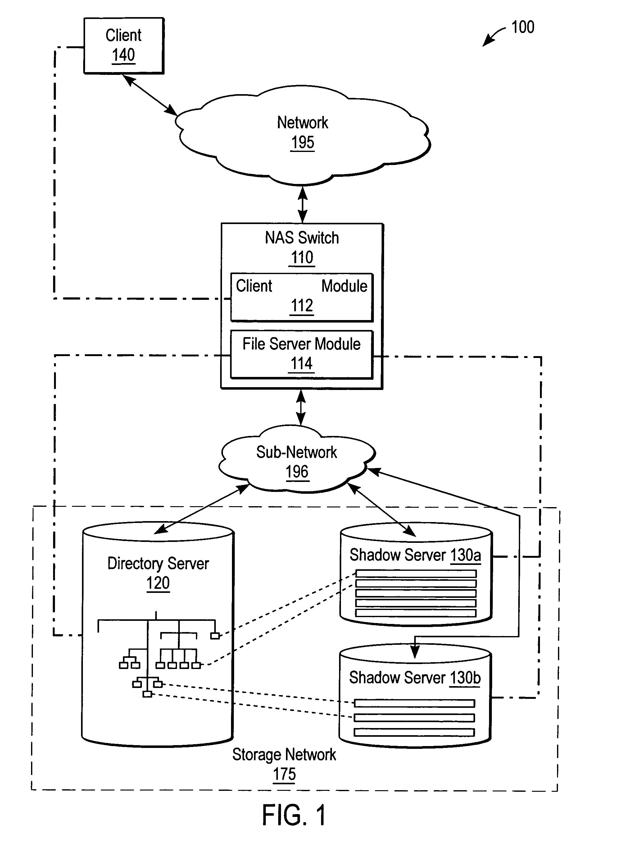
[0014]In still embodiment, the directory file server provides a centralized service to decentralized file servers on the storage network. Because the directory file server provides access to an extended capacity of storage, spanning across several shadow file servers of comparable capacity, the centralized service on the directory file server can be applied against this extended capacity. For example, a file locking service that preserves data integrity during multiple accesses is able to lock files from the directory file server, thereby preventing write requests to associated data on several shadow file servers.

Problems solved by technology

By contrast, more expensive and powerful SAN (Storage Area Network) file servers use resources connected by Fibre Channel on a back-end, or a dedicated network.
However, the benefits of NAS storage networks over SAN storage networks also have drawbacks.
One drawback with NAS file servers is that there is no centralized control.
This is particularly inefficient when there are changes in hardware, but not in the particular files available on the network, such as when a failing NAS file server is swapped out for an identically configured back-up NAS file server.
A related drawback of decentralized control is that services must be separately purchased and installed to each NFS file server.
Furthermore, each installed service consumes data capacity that could be better used to server the main purpose of a storage network, which is to store data.

Method used


Image

  • Extended storage capacity for a network file server
  • Extended storage capacity for a network file server
  • Extended storage capacity for a network file server

Examples


Embodiment Construction

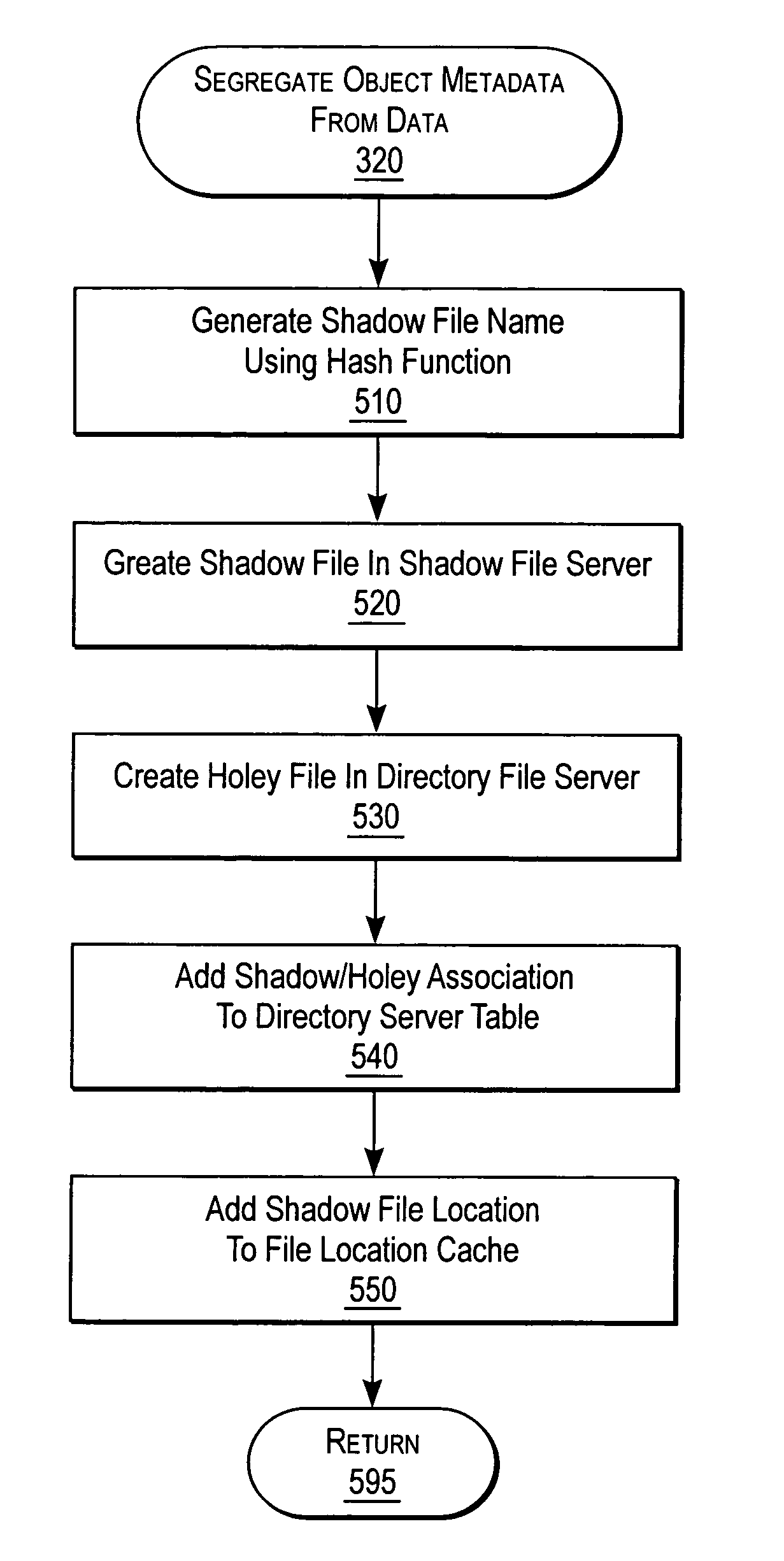
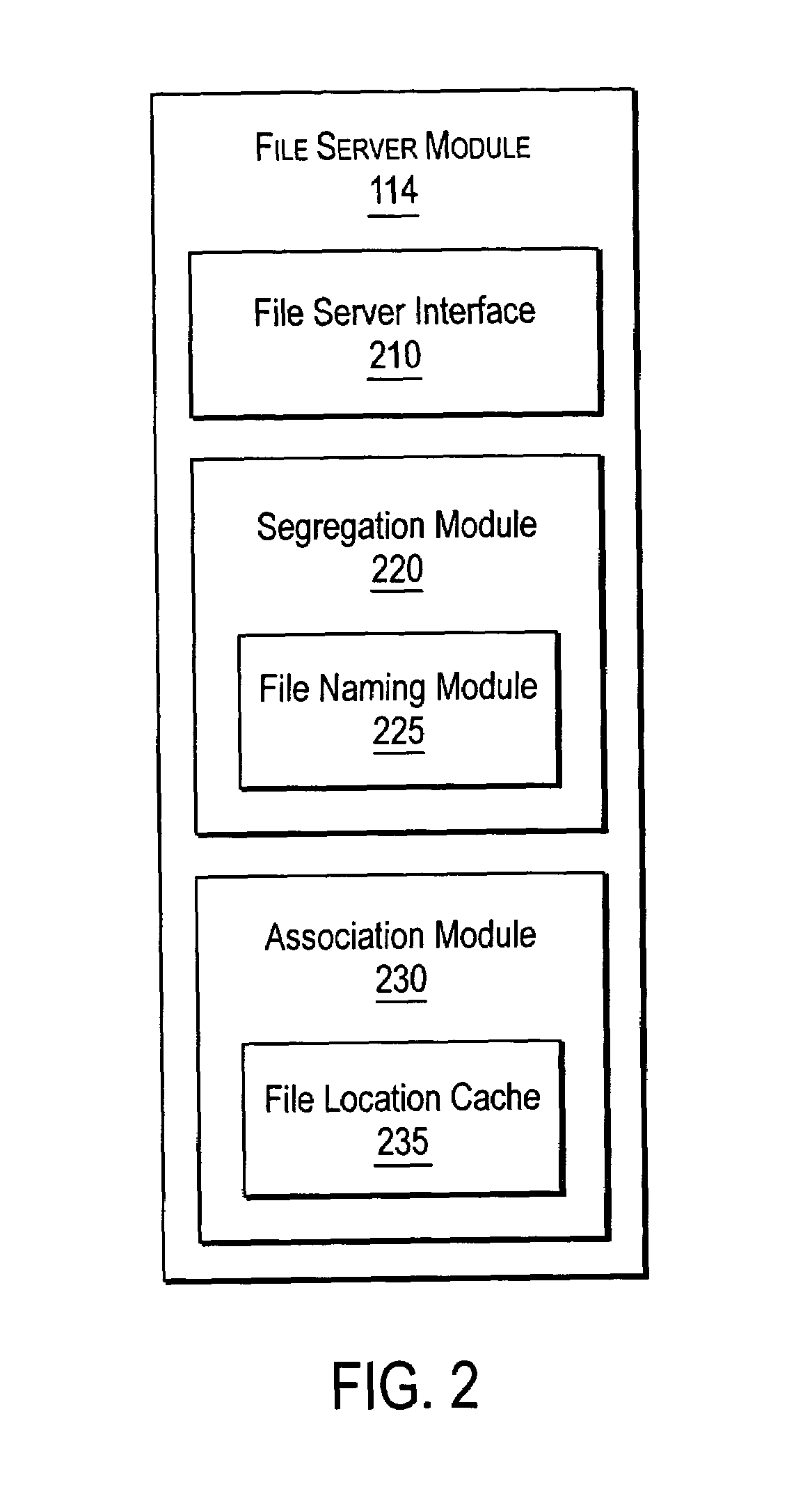
[0021]The present invention provides extended storage capacity for a network file server. A NAS (Network Attached Storage) switch in the data path of a client and NAS file servers on the storage network, stores directory metadata separately from associated data to extend the storage capacity of a directory file server. Some embodiments of a system are described with respect to FIGS. 1–2, and some embodiments of a method operating therein are described with respect to FIGS. 3–6.

[0022]The accompanying description is for the purpose of providing a thorough explanation with numerous specific details. Of course, the field of storage networking is such that many different variations of the illustrated and described features of the invention are possible. Those skilled in the art will thus undoubtedly appreciate that the invention can be practiced without some specific details described below, and indeed will see that many other variations and embodiments of the invention can be practiced ...


PUM


Abstract

A NAS switch provides extended storage capacity to a file server in a decentralized storage network such as a NAS (Network Attached Storage) storage network. The NAS switch sits in the data path of a client on the front end and a directory file server and shadow file servers on the back end. A segregation module in the NAS switch replicates data from the directory file server to a shadow file server, and then replaces the data in the directory file server with holey files. Holey files, which store a range of consecutive values such as zero with negligible storage space, retain the attributes of the data without retaining its storage consumption. Thus, the directory file server can server as a single directory hierarchy for several shadow file servers containing data beyond a capacity of the directory file server. When the NAS switch receives operations from the client, an association module forwards directory operations to the directory file server and data operations to the shadow file server. The NAS switch also provides services to several shadow file servers from a single directory file server.

Description

CROSS-REFERENCE TO RELATED APPLICATIONS[0001]This application claims priority under 35 U.S.C. § 119(e) to: U.S. Provisional Patent Application No. 60 / 465,580, filed on Apr. 24, 2003, entitled “Method and Apparatus to Extend the Storage Capacity to a Network File Server,” by Thomas K. Wong et al.; U.S. Provisional Patent Application No. 60 / 465,579, filed on Apr. 24, 2003, entitled “Method and Apparatus for Transparent File Migration Using the Technique of Namespace Replication,” by Thomas K. Wong et al.; U.S. Provisional Patent Application No. 60 / 465,578, filed on Apr. 24, 2003, entitled “Method and Apparatus for Transparent File Replication Using the Technique of Namespace Replication,” by Thomas K. Wong et al.; and is related to U.S. patent application Ser. No. 10 / 831,376, filed on Apr. 23, 2004, entitled “Transparent File Migration Using Namespace Replication,” by Thomas K. Wong et al.; and U.S. patent application Ser. No. 10 / 831,701, filed on Apr. 23, 2004, entitled “Transparent ...

Claims


Application Information

Patent Timeline
Patent Type & Authority Patents(United States)
IPC IPC(8): G06F12/00G06F17/00G06F17/30H04L29/08
CPCG06F17/30067H04L67/1095H04L67/1097H04L69/329Y10S707/99956Y10S707/955Y10S707/99953Y10S707/99942G06F16/10
Inventor WONG, THOMAS K.TSIRIGOTIS, PANAGIOTISIYENGAR, ANANDCHAWLA, RAJEEV
Owner CISCO TECH INC
Learn More