
Medical procedure table

a medical procedure and table technology, applied in the field of medical procedure tables, can solve the problems of not being able to adapt to the universal market, not being able to portability and cost effectiveness for the ambulatory market, and many prior art medical procedure tables are expensive and difficult to maintain, so as to facilitate the use of accessories and/or the changing of sections

Inactive Publication Date: 2006-07-11
SKRIPPS THOMAS K
View PDF25 Cites 27 Cited by
  • Summary
  • Abstract
  • Description
  • Claims
  • Application Information

AI Technical Summary

Benefits of technology

[0004]It is therefore an object of this invention to provide a medical procedure table that can easily accommodate the use of accessories and / or the changing of sections, such as the main section, leg section, back section and / or head section.
[0005]It is a further object of this invention to provide such a medical procedure table that is inexpensive and easy to maintain.
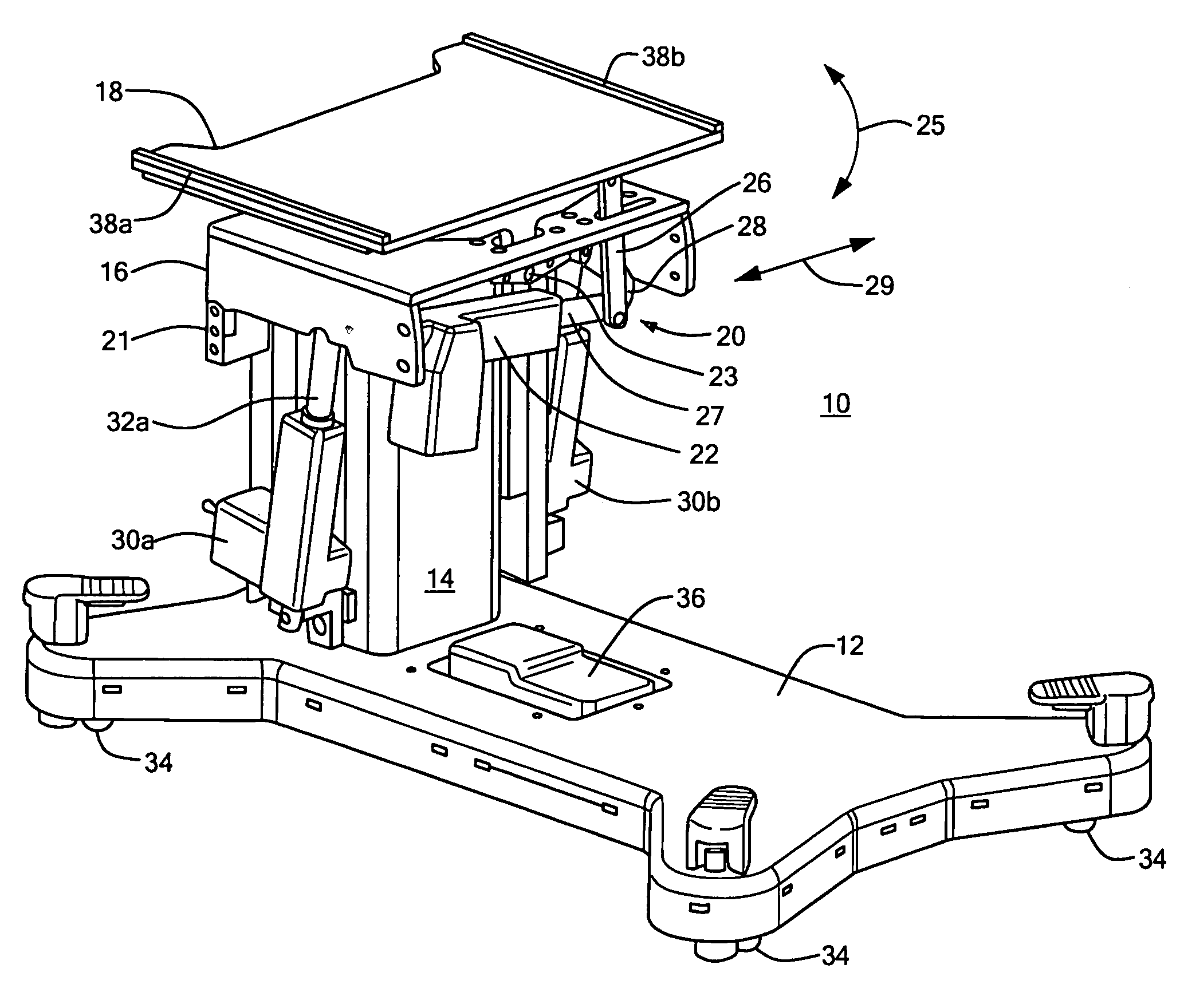
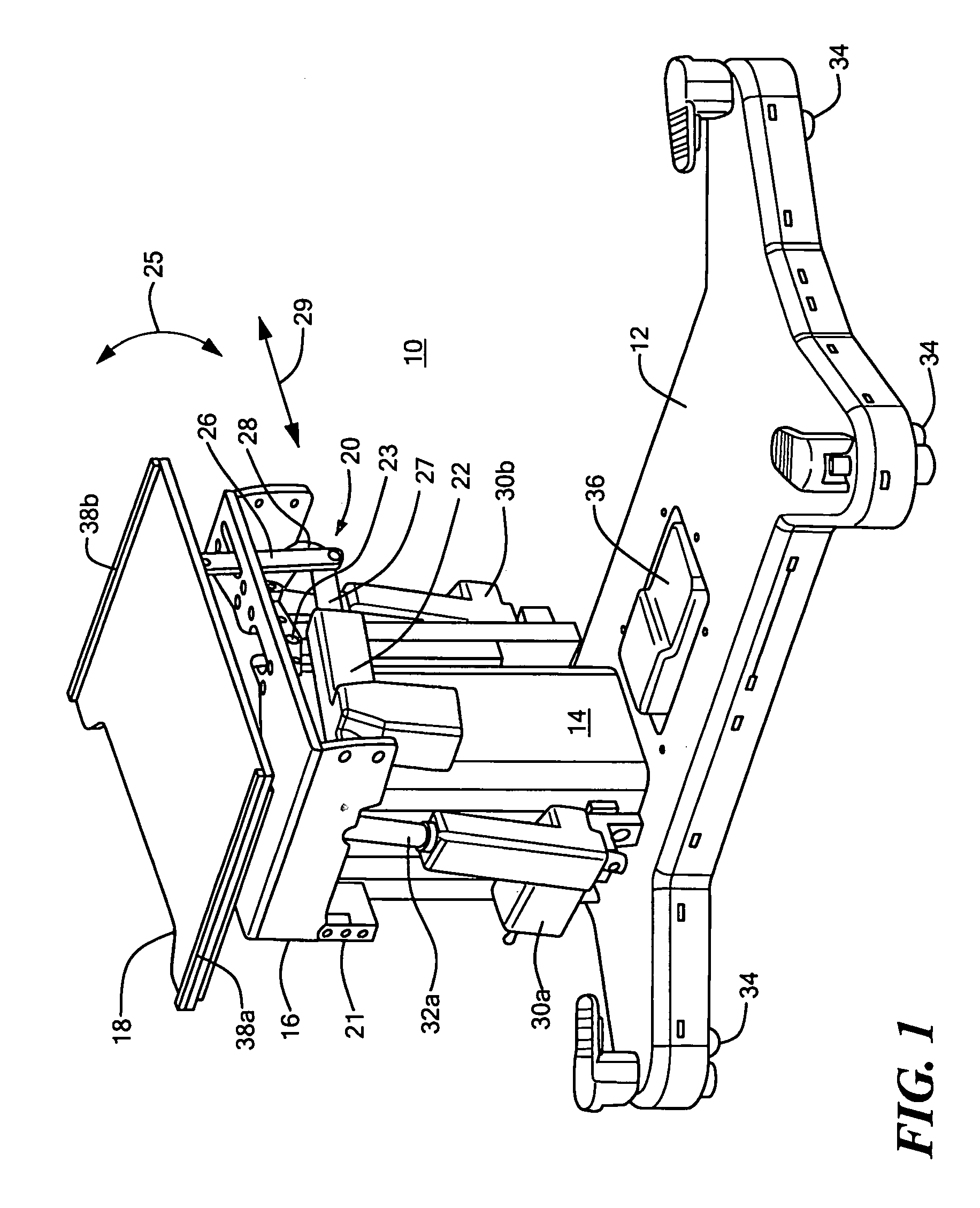
[0006]The invention results from the realization that a less expensive and easier to maintain medical procedure table can be achieved by using a carriage pivotably mounted to a shuttle assembly, a main plate pivotably mounted to the carriage and a roll actuator subsystem including a roll actuator mounted to the carriage and having a stroke motion in a first direction, and a link subsystem connected between the roll actuator and the main plate and configured to translate the stroke motion of the actuator to motion transverse to the first direction to roll the main plate. The subject invention results from the further realization that a more adaptable medical procedure table includes opposing side guide rails on the main plate and a center section that includes opposing side guide rails and opposing side channels readily received over the opposing side guide rails of the main plate. This way, the same base unit can accommodate a wide variety of different table sections and configurations. With built-in rails, the medical procedure table can be used as a stand-alone traction table, without the use of a table top. The subject invention allows many medical procedure table products to be produced from one low-cost table base.

Problems solved by technology

However, no single medical procedure table product is known to have been adaptable as a universal medical procedure table.
Fixed tables have the benefit of interchangeability, but not the portability and cost effectiveness for the ambulatory market.
Moreover, many of the prior art medical procedure tables are expensive and are difficult to maintain.

Method used


Image

  • Medical procedure table
  • Medical procedure table
  • Medical procedure table

Examples


Embodiment Construction

[0032]Aside from the preferred embodiment or embodiments disclosed below, this invention is capable of other embodiments and of being practiced or being carried out in various ways. Thus, it is to be understood that the invention is not limited in its application to the details of construction and the arrangements of components set forth in the following description or illustrated in the drawings. If only one embodiment is described herein, the claims hereof are not to be limited to that embodiment. Moreover, the claims hereof are not to be read restrictively unless there is clear and convincing evidence manifesting a certain exclusion, restriction, or disclaimer.

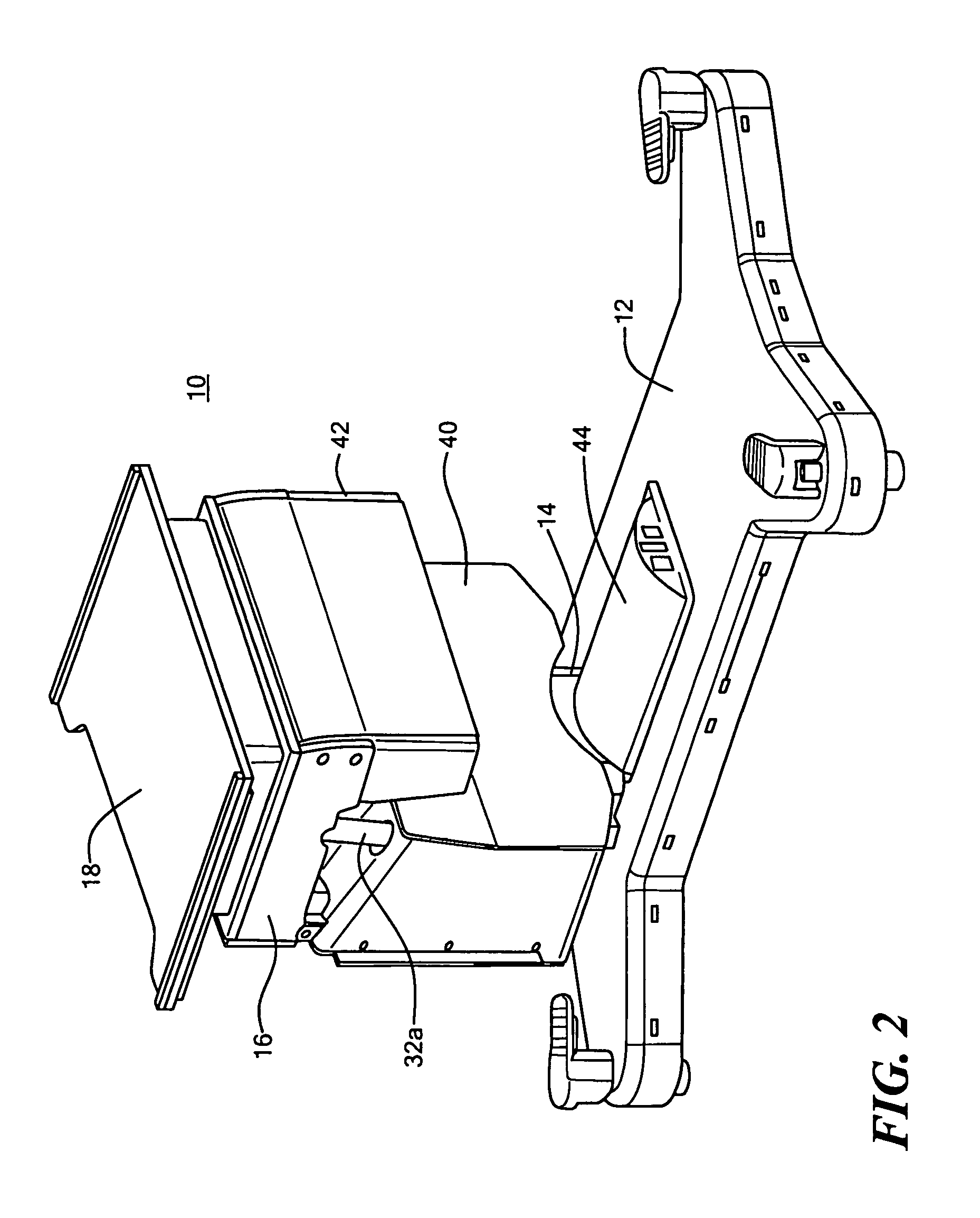
[0033]A medical procedure table 10, FIG. 1, in accordance with this invention includes base plate 12, a base column 70, FIG. 5, shuttle assembly 14, FIG. 1, carriage 16, main plate 18 and roll actuator subsystem 20. Shuttle assembly 14 is telescopingly mounted to the base column which extends upward from base 12. Carriage 1...


PUM


Abstract

A medical procedure table includes a base plate, a base column extending upwards from the base, a shuttle assembly telescopingly mounted to the base column, a carriage pivotably mounted to the shuttle assembly, and a main plate pivotably mounted to the carriage. A roll actuator subsystem includes a roll actuator mounted to the carriage and a piston pivotably connected to an arm, the arm pivotably connected to the main plate, and a linkage pivotably connected between the piston and the carriage.

Description

RELATED APPLICATIONS[0001]This application claims benefit of U.S. Provisional Application No. 60 / 468,157, filed May 6, 2003, which is hereby incorporated by reference.FIELD OF THE INVENTION[0002]This invention relates to medical procedure tables and more specifically a portable modular medical procedure table.BACKGROUND OF THE INVENTION[0003]The field of medical procedures and surgery has become highly specialized. Very focused procedures are being performed in dedicated environments, creating distinctly separate industries, such as orthopedic surgery, ambulatory surgery, pain management, and endovascular surgery, etc. Equipment has been designed for these markets, which addresses the specific needs of each market. However, no single medical procedure table product is known to have been adaptable as a universal medical procedure table. Fixed tables have the benefit of interchangeability, but not the portability and cost effectiveness for the ambulatory market. Most operating room ta...

Claims


Application Information

Patent Timeline
Patent Type & Authority Patents(United States)
IPC IPC(8): A61G13/04
CPCA61G13/04A61G13/08A61G13/10A61G13/12A61G2210/50A61G13/121A61G13/1245A61G2200/34
Inventor SKRIPPS, THOMAS K.
Owner SKRIPPS THOMAS K
Learn More