Methods and apparatus for pressure compensation in a mass flow controller

a mass flow controller and pressure compensation technology, applied in adaptive control, process and machine control, instruments, etc., can solve the problems of incongruous and undesirable performance of the mass flow controller, laborious procedure, more skilled operators and specialized equipment,

Inactive Publication Date: 2006-07-11
BROOKS INSTRUMENT
View PDF94 Cites 88 Cited by
  • Summary
  • Abstract
  • Description
  • Claims
  • Application Information

AI Technical Summary

Benefits of technology

[0018]One aspect of the present invention includes a method of dead volume compensation, the method comprising acts of predicting a response of a sensor to a fluid filling a dead volume due to pressure changes in a fluid flow path, and modifying a sensor output signal provided by the sensor based on the predicted response to essentially remove false flow information from the sensor output signal.

Problems solved by technology

However, it should be appreciated that some mass flow controllers may not employ a bypass, as such, all of the fluid may flow through the sensor conduit.
In addition, conventional mass flow controllers may exhibit certain non-uniformities particular to a combination of components used in the production of the mass flow controller which results in inconsistent and undesirable performance of the mass flow controller.
As is known to those skilled in the art, the process of tuning and / or calibrating a mass flow controller is an expensive, labor intensive procedure, often requiring one or more skilled operators and specialized equipment.
Although the use of additional tuning and / or calibration with different fluids and at different operating conditions can be used to improve the performance of the mass flow controller, this type of surrogate tuning and / or calibration is time consuming and expensive, as the tuning and / or calibration procedures must be repeated for at least each surrogate fluid and likely must be repeated for a number of different operating conditions with each surrogate fluid.
Pressure regulators generally do not operate error free and may introduce pressure transients, or other deviations from the desired pressure into the flow path.
These deviations may have deleterious effects on the performance of the mass flow controller.
Often the mass flow controller must absorb these undesirable pressure transients as best as possible, and these undesirable transients typically degrade the accuracy of control and quality of performance of the mass flow controller.

Method used


Image

  • Methods and apparatus for pressure compensation in a mass flow controller
  • Methods and apparatus for pressure compensation in a mass flow controller
  • Methods and apparatus for pressure compensation in a mass flow controller

Examples


Embodiment Construction

[0061]This application contains subject matter that is related to U.S. patent application Ser. No. 10 / 131,603, entitled SYSTEM AND METHOD FOR A MASS FLOW CONTROLLER, filed Apr. 24, 2002, which is herein incorporated by reference in its entirety.

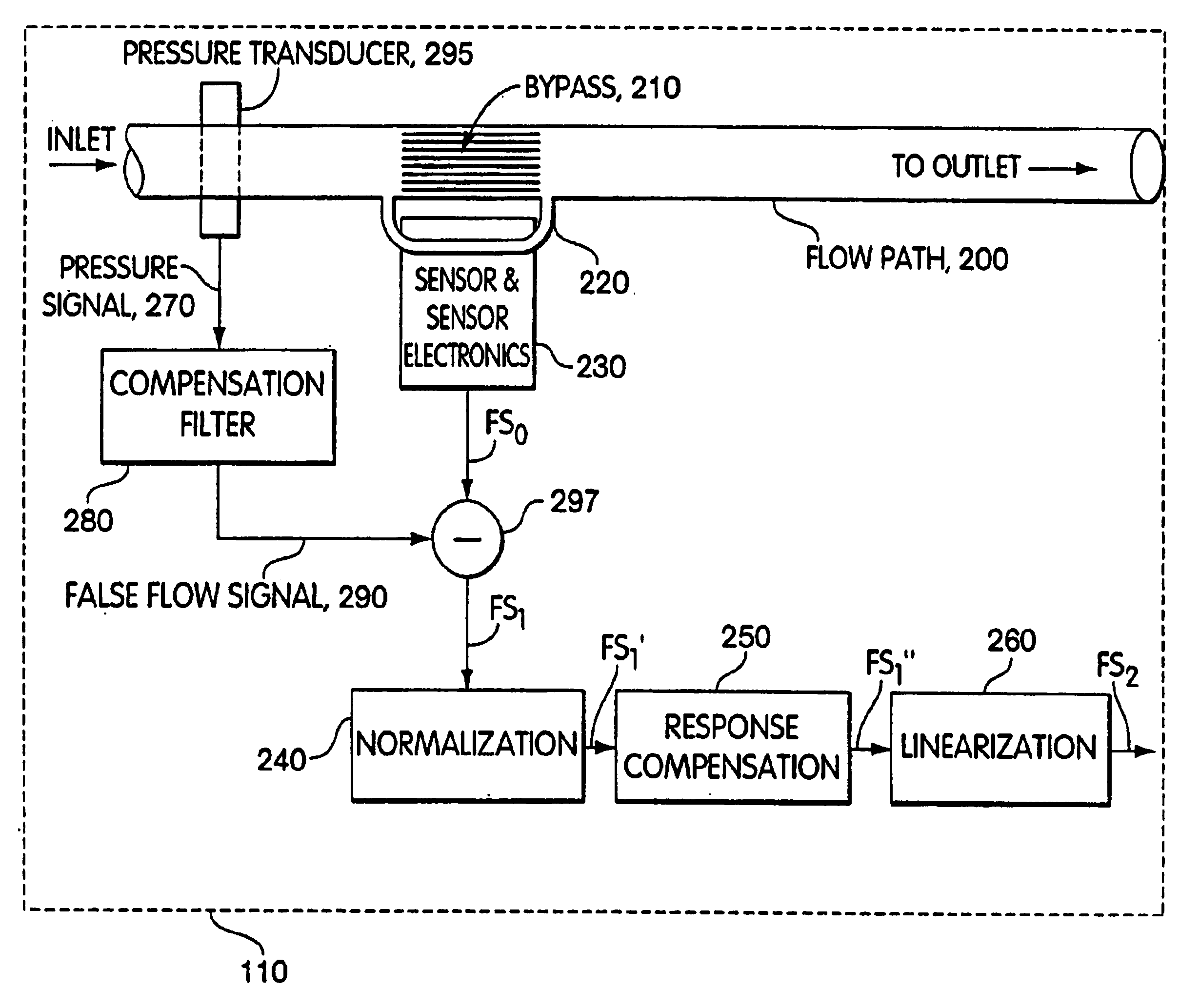
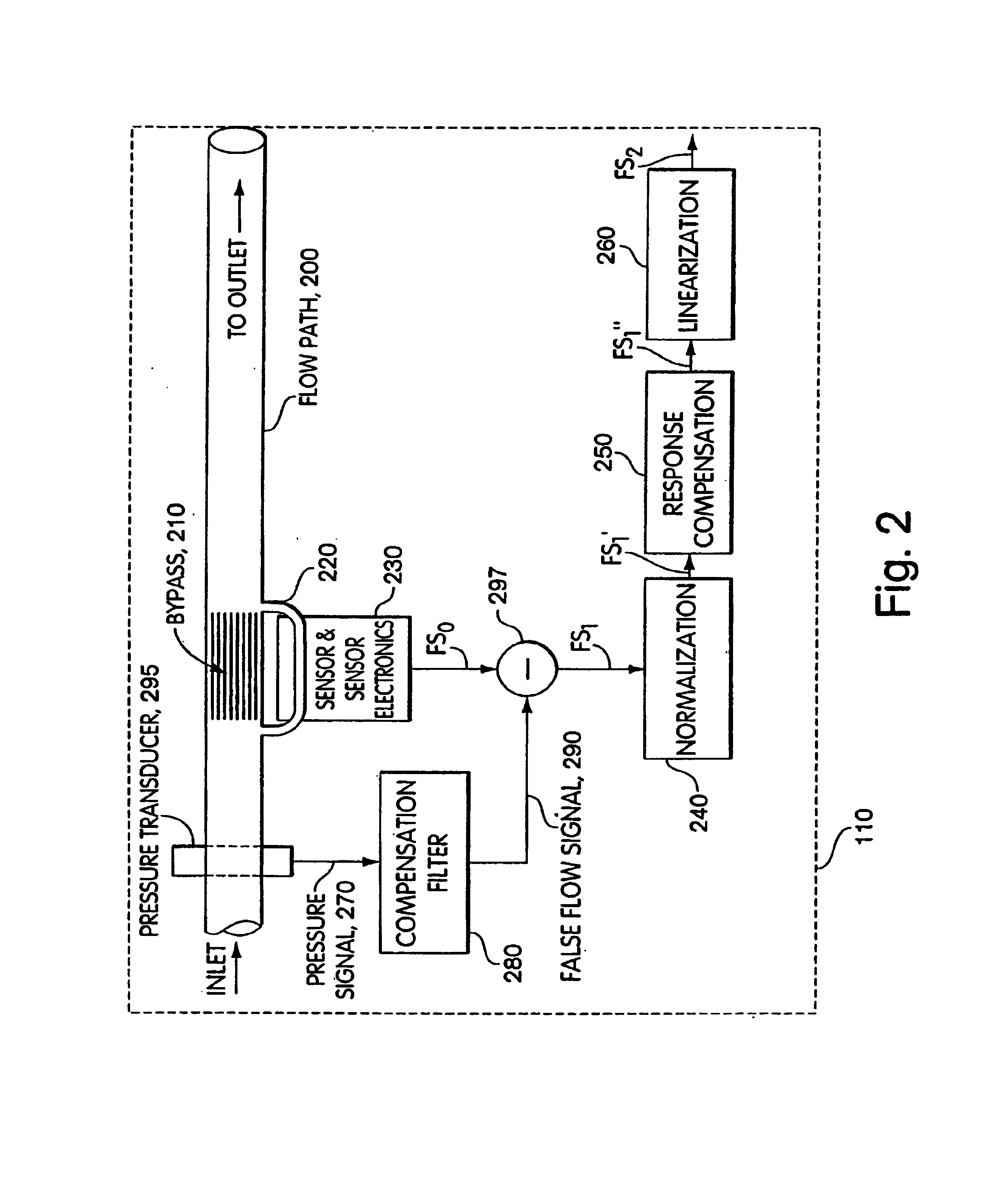
[0062]Typically a fluid flow path exists in a pressure environment. The pressure environment may include the pressure at the inlet side of the flow path (referred to as inlet pressure), and pressure at the outlet side of the valve (referred to as outlet pressure), and other pressures within the environment. For example, the pressure environment of the flow path may also include pressure differentials such as, for example, the pressure drop across a bypass or across a valve. The pressure environment may also include various pressure transients including pulses introduced by a regulator, turbulence caused by the geometry of a flow sensor, or various other pressure perturbations. However, the pressure environment is not often monitored. As such,...


PUM


Abstract

Performance of mass flow controller may be vulnerable to pressure transients in a flow path to which the controller is coupled for the purpose of controlling the fluid flow. A system and method are provided for reducing or eliminate performance degradations, instabilities, and / or inaccuracies of a mass flow controller caused by changes in the pressure environment. In particular, a method and system are provided for compensating for pressure transients in the pressure environment of a flow path and mass flow controller.

Description

RELATED APPLICATIONS[0001]This application claims priority under 35 U.S.C. § 119(e) to U.S. Provisional Application Ser. No. 60 / 397,285, entitled “METHODS AND APPARATUS FOR PRESSURE COMPENSATION IN A MASS FLOW CONTROLLER,” filed on Jul. 19, 2002, which is herein incorporated by reference in its entirety.FIELD OF THE INVENTION[0002]The present invention relates generally to a method and system for controlling the flow rate of a fluid, and more particularly to methods and systems involving mass flow controllers.BACKGROUND OF THE INVENTION[0003]Many industrial processes require precise control of various process fluids. For example, in the pharmaceutical and semiconductor industries, mass flow controllers are used to precisely measure and control the amount of a process fluid that is introduced to a process chamber. The term fluid is used herein to describe any type of matter in any state that is capable of flow. It is to be understood that the term fluid applies to liquids, gases, and...

Claims


Application Information

Patent Timeline
Patent Type & Authority Patents(United States)
IPC IPC(8): G01F1/00G05B13/04G05D7/06
CPCG01F1/696G01F1/86G05D7/0635G05B13/042G01F15/024Y10T137/0379Y10T137/7759Y10T137/7761Y10T137/7762G05D7/06
Inventor LULL, JOHN MICHAELWANG, CHIUNSAGGIO, JR., JOSEPH A.
Owner BROOKS INSTRUMENT
Why Eureka
Try Eureka