Multi-end strand predetermined tension controller

a predetermined tension and controller technology, applied in the direction of thin material handling, tufting apparatus, filament handling, etc., can solve the problems of carpet product being rejected, strands in the web are significantly higher tension, and the effect could require excessive tip shearing

Inactive Publication Date: 2006-07-11
MFG DESIGNS & SOLUTIONS
View PDF4 Cites 2 Cited by
  • Summary
  • Abstract
  • Description
  • Claims
  • Application Information

AI Technical Summary

Benefits of technology

[0011]It is a further object of the invention to utilize an overfeed roll and an underfeed roll to create slack or tension on strands based upon the pre-determined settings for each of the strands.

Problems solved by technology

In fact, some problems can occur when particular strands in a web are at a significantly higher tension than others.
When a higher tension yarn is run through the tufting machine, undesired effects could include the tufting of loops which are not the same height as those from “looser” yarn ends.
If one were attempting to tuft a particular level over a section of carpet, the presence of a higher or a lower loop could be noticeable and cause the carpet product to be rejected.
In cut pile carpets such an effect could require excessive tip shearing.
If the tension is already too low on a particular fibre, too much alack could be created, especially if it sticks to the first roller.
Entanglement with the other yarns could easily occur in such event.
However, if any of the yarns are tighter than desired, there does not appear to be a way to loosen the tension on selected yarn strands.
While the applicant's device shown and described in the '319 patent is a significant improvement over the prior art, if a strand become loose and continues to get looser and looser, this problem cannot be corrected by this prior art device.
This device appears to treat all the yarns driven by a spool together and does not appear to provide for individual yarn tension control.

Method used


Image

  • Multi-end strand predetermined tension controller
  • Multi-end strand predetermined tension controller
  • Multi-end strand predetermined tension controller

Examples


Embodiment Construction

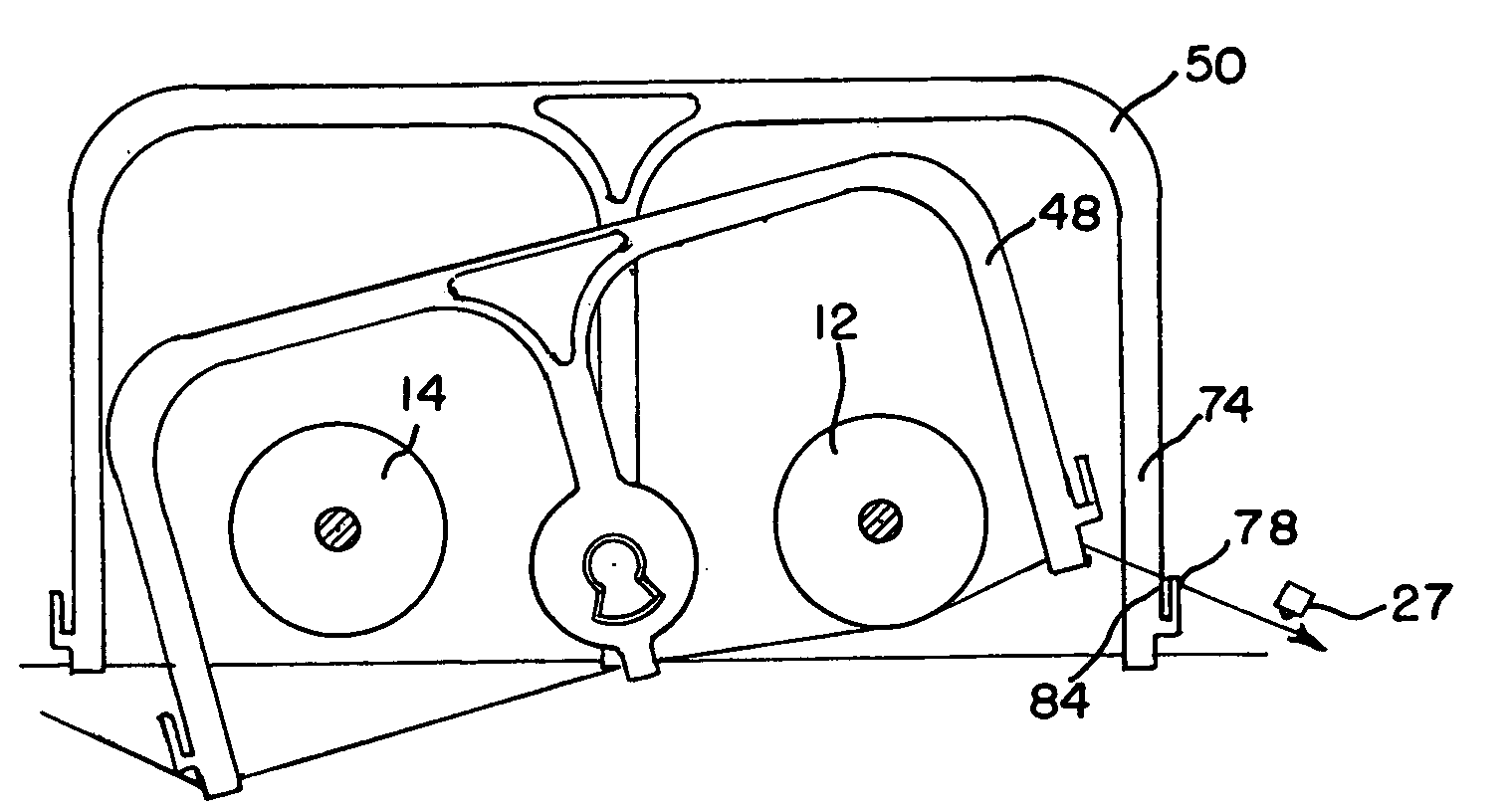
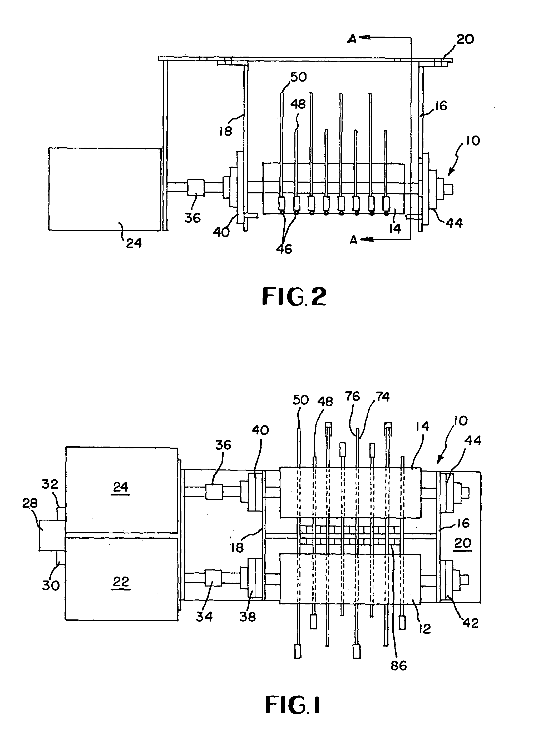
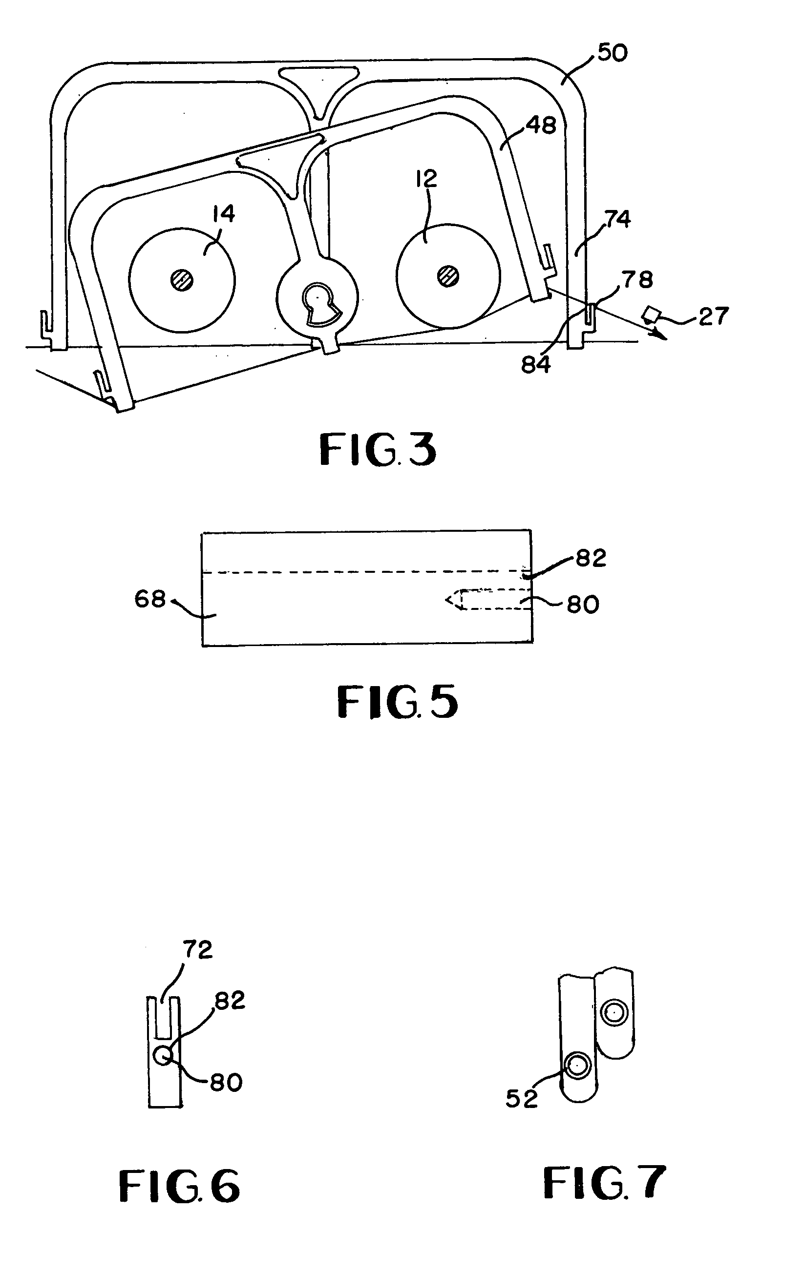
[0023]FIG. 1 shows a bottom view of a tension controller 10. Underfeed roller or slower roller 12 is preferably parallel to overfeed or over speed roller 14 with the rollers 12,14 supported by supports 16,18 from a platform 20. The embodiment of the platform 20 is illustrated located above the rollers 12,14. In other embodiments, the platform 20 can be located below the rollers 12,14 or otherwise. Furthermore, a plurality of platforms 20 or other structures could be utilized to support the rollers 12,14.

[0024]The rollers 12,14 are illustrated operably coupled or connected to motors 22,24. The motors are preferably variable speed motors. The motor 24 preferably drives the over feed roller 14 at a speed faster than the speed of supply of strand 26 so that the surface of the roller 14 is traveling at a speed faster than the speed of the strand 26 or strands 26 which are fed to a downstream machine (not shown). The downstream machine could be a tufting machine or a warper, or other appr...


PUM


Abstract

A multi-end strand tension controller has an overfeed roll and an underfeed roll with strand engagement surfaces. Depending on the outgoing tension, the strand positioner selectively apply the strand against one of the underfeed rollers to adjust the tension and the output of the tension controller. The underfeed roller is fed at a speed slower than the speed of the strand while the overfeed roller is fed at a speed greater than the speed of the feed of the strand. Multiple strands forming the web can be provided utilizing a controller and different predetermined tensions may be applied to each of the individual strands based upon loading of individual strand positioners.

Description

FIELD OF THE INVENTION[0001]The present invention relates to an apparatus which equalizes tension (i.e., reduces tension in over tension yarn while increasing tension in loose yarn), among a web of a multiplicity of strands, and more particularly to an apparatus designed to overfeed tighter strands and simultaneously underfeed loose strands in order to provide strands with each strand having a predetermined desired tension to a downstream apparatus.DETAILED DESCRIPTION OF RELATED ART[0002]Many industry segments utilize multiple strands of elongated elements in various processes. In some processes, multiple strands are preferably fed at a substantially uniform tension to reduce or prevent unwanted effects. Various industries including the carpet industry, textile industry, tire cord industry, and others have processes where multiple strands are preferably fed at substantially the same tension. In fact, some problems can occur when particular strands in a web are at a significantly hi...

Claims


Application Information

Patent Timeline
Patent Type & Authority Patents(United States)
IPC IPC(8): B65H23/16
CPCB65H59/18B65H59/36D05C15/18B65H2701/38B65H2701/31
Inventor HASELWANDER, JOHN G.
Owner MFG DESIGNS & SOLUTIONS
Why Eureka
Try Eureka