Lighting apparatus with flexible OLED area illumination light source and fixture

a light source and flexible technology, applied in the direction of discharge tube/lamp details, solid-state devices, organic semiconductor devices, etc., can solve the problems of difficult handling and shipping large volume of conventional illumination devices such as incandescent or fluorescent light bulbs, and difficult to manufacture and integrate into single area illumination devices. achieve the effect of saving considerable storage space and efficiently stor

Inactive Publication Date: 2006-07-11
GLOBAL OLED TECH
View PDF8 Cites 74 Cited by
  • Summary
  • Abstract
  • Description
  • Claims
  • Application Information

AI Technical Summary

Benefits of technology

[0008]The present invention has the advantage of providing a lighting apparatus having a light source that can be stored efficiently in a planar configuration, thereby saving considerable storage space. Another advantage is that the planar flexible light sources are not fragile and can be packaged in thin, unpadded packaging.

Problems solved by technology

These multiple devices are expensive and complex to manufacture and integrate into single area illumination devices.
Moreover, LED devices provide point sources of light that are not preferred for area illumination.
Conventional illumination devices such as incandescent or fluorescent light bulbs are bulky, fragile, and problematic to handle and ship.
Although the bulbs are filled with gas, the glass tubes are easily broken and occupy substantial space, especially in comparison to the actual light emitting area or material of the device.
Existing solid-state lighting elements may be planar and hence easy and cost-effective to ship but do not address the need for lighting elements that have a variety of conventional three-dimensional shapes as found, for example, in light bulbs for decorative lighting.

Method used


Image

  • Lighting apparatus with flexible OLED area illumination light source and fixture
  • Lighting apparatus with flexible OLED area illumination light source and fixture
  • Lighting apparatus with flexible OLED area illumination light source and fixture

Examples


Embodiment Construction

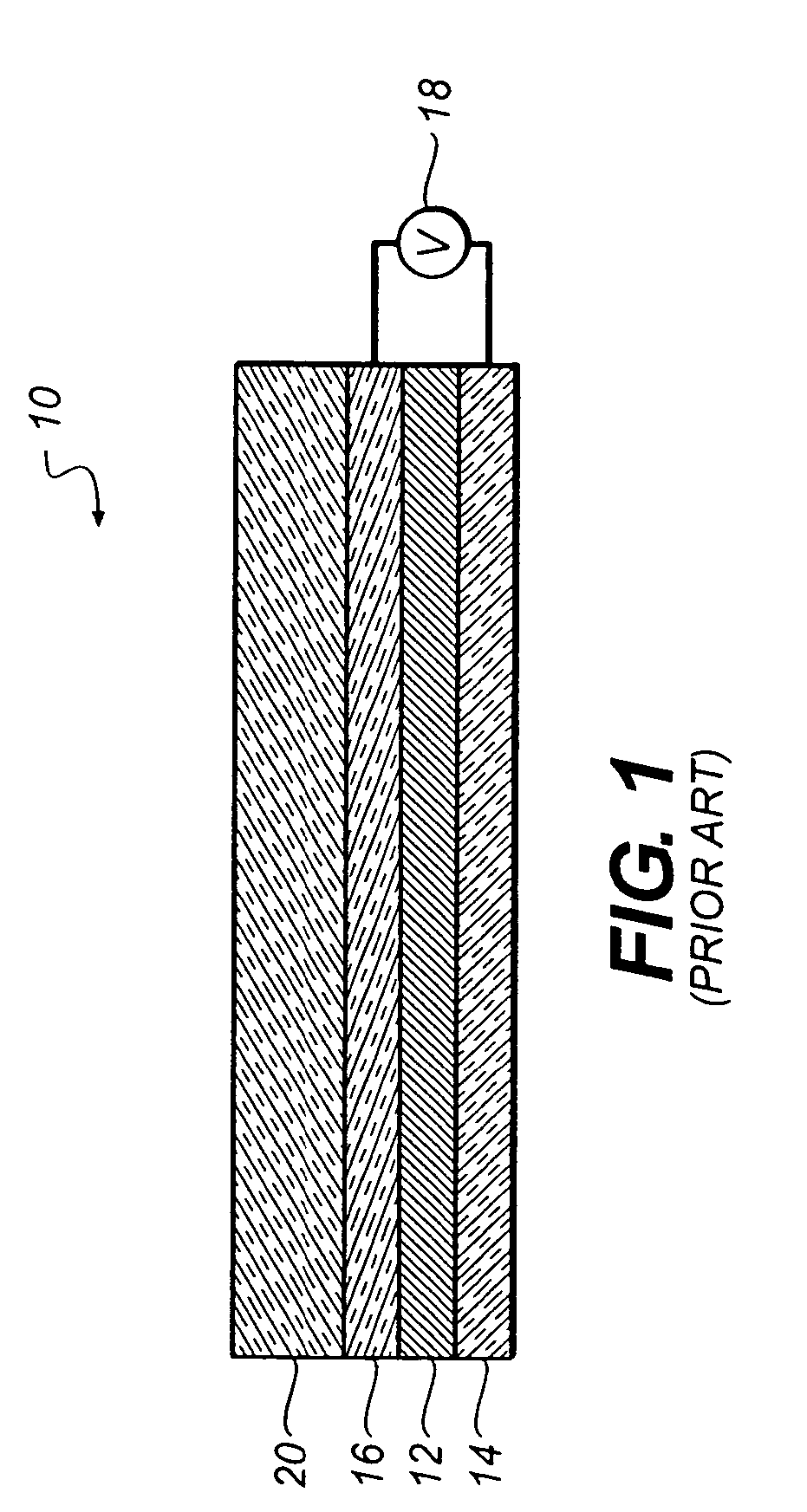
[0025]FIG. 1 is a schematic diagram of a prior art OLED light source 10 including an organic light emitting layer 12 disposed between two electrodes, e.g. a cathode 14 and an anode 16. The organic light emitting layer 12 emits light upon application of a voltage from a power source 18 across the electrodes. The OLED light source 10 typically includes a substrate 20 such as glass or plastic. It will be understood that the relative locations of the anode 16 and cathode 14 may be reversed with respect to the substrate. The term OLED light source refers to the combination of the organic light emitting layer 12, the cathode 14, the anode 16, and other layers described below.

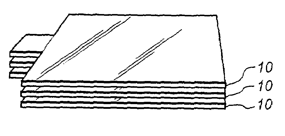
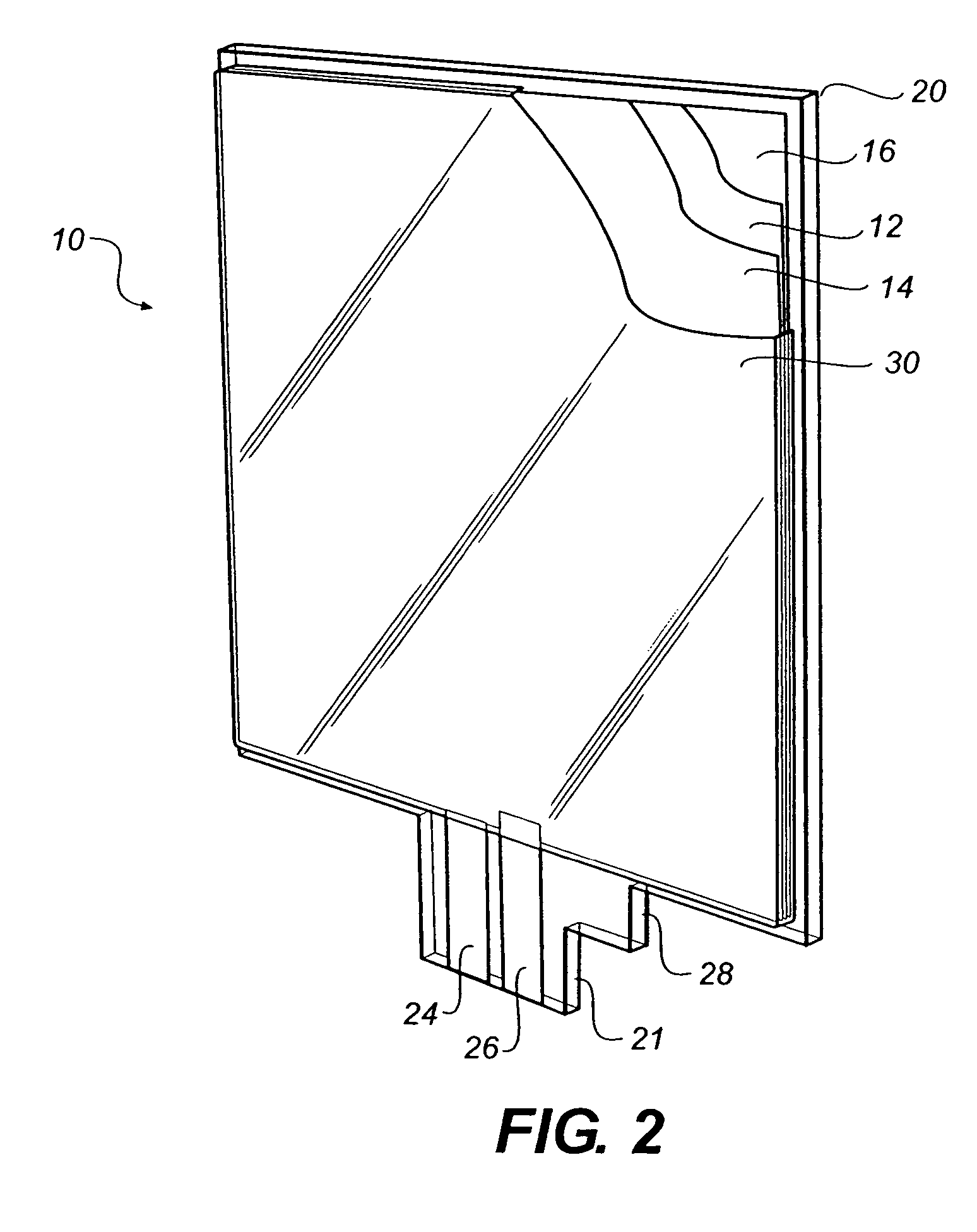
[0026]Referring to FIG. 2, a solid-state area illumination light source, includes a planar flexible substrate 20, a flexible organic light emitting diode (OLED) layer 12 deposited on the flexible substrate, the organic light emitting diode layer including first and second electrodes 14 and 16 for providing electrical ...


PUM


Abstract

Lighting apparatus includes a solid-state area illumination light source, having: a planar flexible substrate, a flexible organic light emitting diode (OLED) layer deposited on the flexible substrate, the organic light emitting diode layer including first and second electrodes for providing electrical power to the OLED layer, a flexible encapsulating cover covering the OLED layer, and first and second conductors electrically connected to the first and second electrodes, and extending beyond the encapsulating cover for making electrical contact to the first and second electrodes by an external power source, whereby the light source may be stored in a space saving planar configuration; and a lighting fixture for removably receiving and holding the light source in a curved 3 dimensional configuration, the lighting fixture including a support for holding the light source in the curved configuration and contacts for providing electrical contact between said first and second conductors and an external power source.

Description

CROSS REFERENCE TO RELATED APPLICATIONS[0001]This application is a divisional of application Ser. No. 10 / 156,396, filed May 28, 2002 now U.S. Pat. No. 6,771,021.FIELD OF THE INVENTION[0002]The present invention relates to the use of organic light emitting diodes for area illumination.BACKGROUND OF THE INVENTION[0003]Solid-state lighting devices made of light emitting diodes are increasingly useful for applications requiring robustness and long-life. For example, solid-state LEDs are found today in automotive applications. These devices are typically formed by combining multiple, small LED devices providing a point light source into a single module together with glass lenses suitably designed to control the light as is desired for a particular application (see, for example WO99 / 57945, published Nov. 11, 1999). These multiple devices are expensive and complex to manufacture and integrate into single area illumination devices. Moreover, LED devices provide point sources of light that a...

Claims


Application Information

Patent Timeline
Patent Type & Authority Patents(United States)
IPC IPC(8): H05B33/00H01L51/50F21K99/00H01L51/52H05B33/02H05B33/04H05B33/06H05B33/12
CPCF21K9/135F21S6/004F21S6/005F21V19/0005F21V3/00F21S6/002F21S6/00F21S8/04F21Y2101/02F21Y2105/00F21Y2105/008H01L51/5237H01L2251/5338H01L2251/5361Y02B20/36H01R12/721F21K9/232F21Y2115/15Y02B20/30H10K50/841H10K2102/311H05B33/00
Inventor COK, RONALD S.
Owner GLOBAL OLED TECH
Why Eureka
Try Eureka