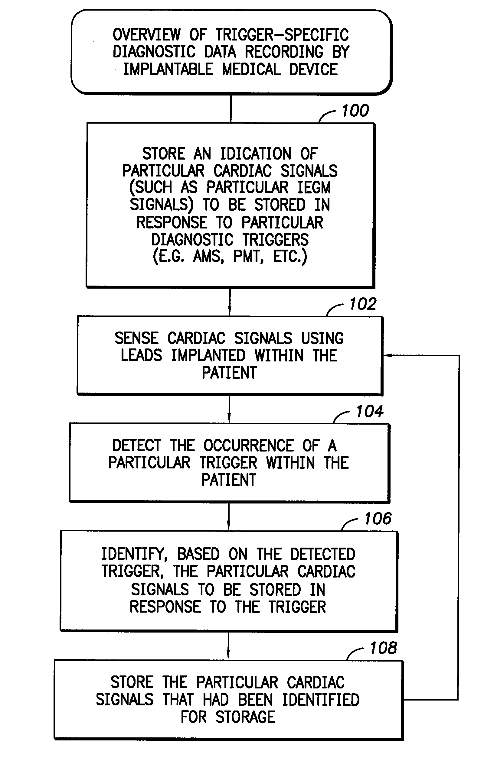
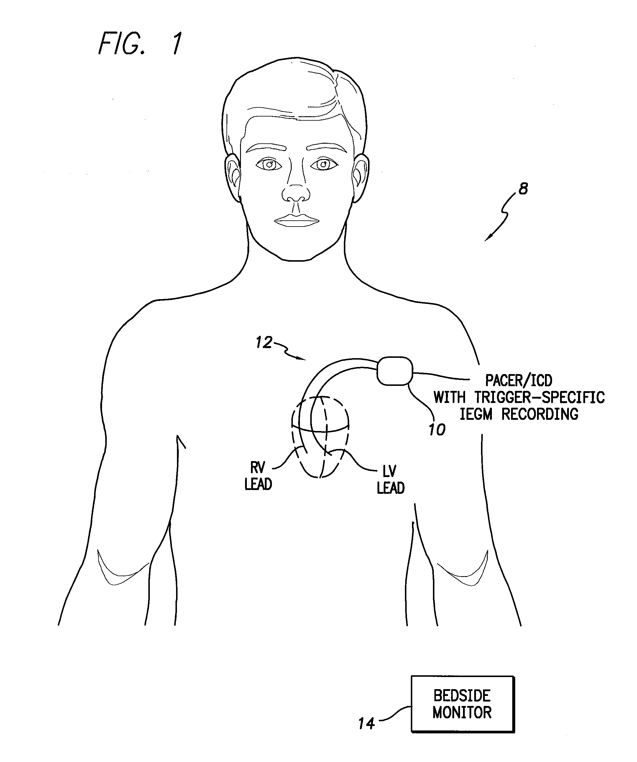
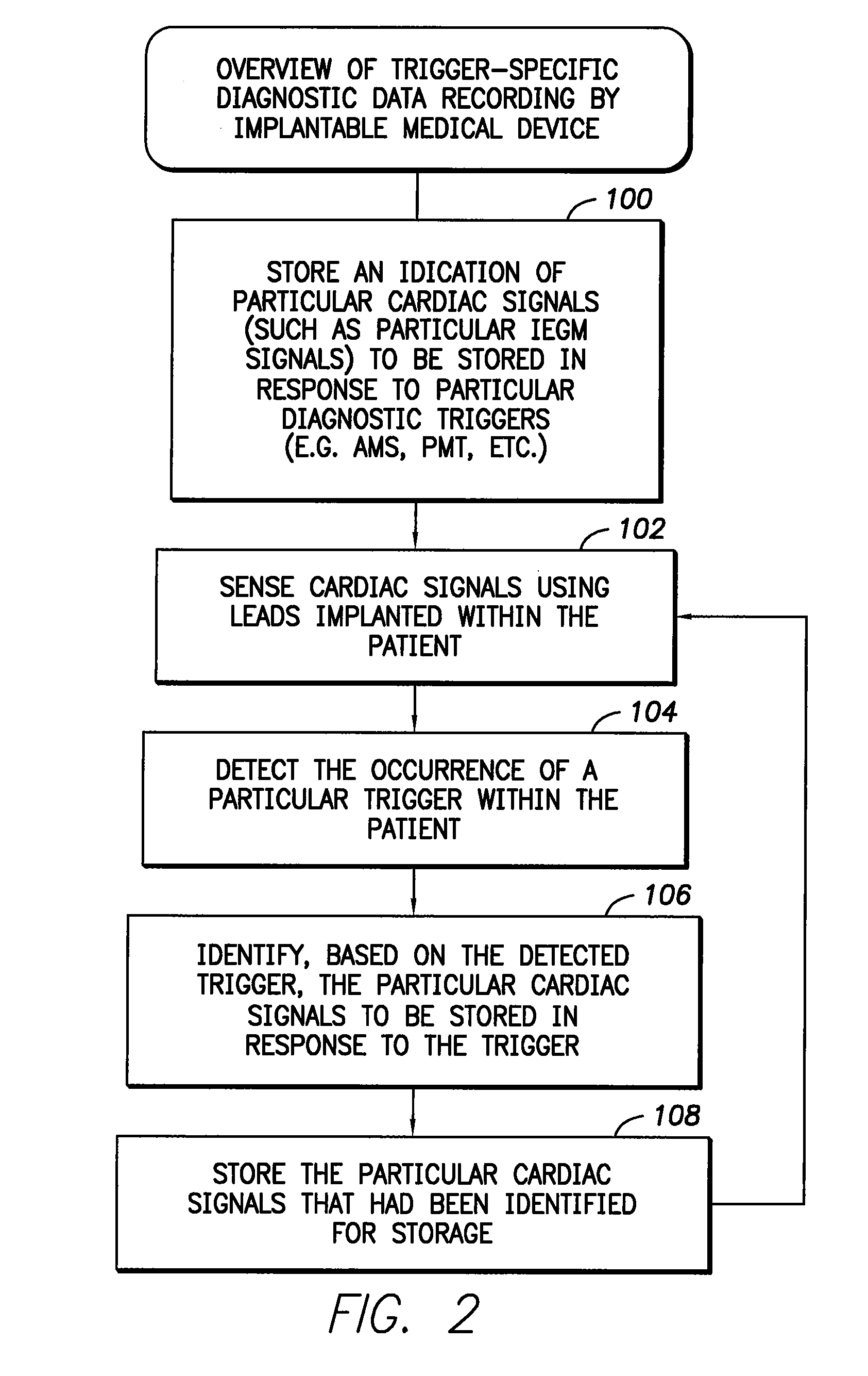
[0009]In an exemplary embodiment, a method is provided for use by an implantable
medical device such as a pacemaker for controlling the recording of signals by the device, wherein the device is capable of recording different types of signals in response to different diagnostic triggers. The method comprises: storing an indication of particular signals (such as IEGMs) to be stored in response to particular diagnostic triggers; sensing signals within the patient; detecting the occurrence of a particular trigger within the patient; identifying, based on the trigger, the particular signals to be stored in response to the trigger; and then storing the particular signals identified for storage. In an illustrative example, the signals to be stored are cardiac signals such as IEGMs. The indication of the particular IEGMs or other cardiac signals to be stored is preferably initially provided by a physician or other clinician via an external programmer. In this manner, the physician can select different IEGMs to be stored in response to different diagnostic triggers, thereby providing greater diagnostic flexibility to the physician while reducing the amount of IEGM data the device itself must
record, at least as compared to those devices that
record all selected IEGMs in response to the occurrence of any selected triggers.
[0010]In one example, the physician also initially selects the particular diagnostic triggers to be used via the external programmer. Examples include: an AMS detection trigger; a PMT trigger; an AT trigger, an AF trigger, a VT trigger, a VF trigger and a consecutive PVC trigger (i.e. two or more PVCs occurring in sequence). The physician also selects the particular IEGMs to be stored for each selected trigger. IEGMs are selected by specifying different
electrode combinations from among the electrodes available to the device, such as AR TIP, AR RING, VL TIP, AL RING, AL COIL, VR TIP, VR RING, RV COIL, VL TIP, VL RING, VL COIL and device housing electrodes, as well as shorted combinations of the electrodes (wherein two or more individual electrodes are employed as a single combined
electrode). Then, during use, whenever a particular one of the selected triggers is detected, the implantable device records only those IEGMs that had been selected for that particular trigger. The IEGMs are eventually transmitted to the external programmer for display thereon. In this manner, the physician can conveniently review the particular IEGMs of interest for a given trigger. Moreover, the implantable device need only record the particular IEGMs of interest for a particular trigger, rather than all selected IEGMs, thus saving considerable storage space.
[0011]In general, any number of triggers can be selected by a physician to trigger the recording of IEGMs or other
diagnostic data, and any number of IEGMs can be selected for use with each trigger, allowing considerable flexibility. In practice, to limit the amount of IEGM data that needs to be stored within the implantable device, the device may be configured to permit only a few IEGMs to be specified for each trigger. For example, the device may be equipped to store only two or three IEGMs for each detected trigger. The particular IEGMs to be recorded may, of course, differ depending upon the particular trigger that is detected. As can be appreciated, a wide variety of implementations can be exploited, wherein various limitations are imposed either on the choice of IEGMs, the choice of triggers, or both, so as to reduce the amount of data that needs to be stored within the device itself. Preferably, a
FIFO memory is employed so that, if previously recorded IEGM
data needs to be erased to accommodate newly recorded data, the oldest data is overwritten while more recently recorded data is preserved.
[0013]Whenever an atrial-related trigger is detected, both atrial channel IEGMs are recorded, whereas only the primary ventricular channel IEGM is recorded. In contrast, whenever a ventricular-related trigger is detected, both ventricular channel IEGMs are recorded, whereas only the primary atrial channel IEGM is recorded. Thus,
atrial arrhythmias and other anomalous atrial events, such as PMTs, trigger the recording of two atrial IEGMs and one ventricular IEGM; whereas ventricular arrhythmias and other anomalous ventricular events, such as consecutive PVCs, trigger the recording of two ventricular IEGMs and one atrial IEGM. In this manner, the physician is provided with a total of three IEGMs in response to each trigger event, with the particular IEGMs automatically selected based on the chambers in which the event occurred. The device saves memory resources by recording only three of the four sensed IEGM channels.
[0018]In an another exemplary embodiment, a method is provided for use by an external
system (such as an external programmer) for controlling the display of signals recorded by an implantable
medical device capable of recording different signals within a patient in response to different diagnostic triggers detected within the patient. During an initial
programming session, the external
system receives user selections of particular signals to be recorded by the implantable medical device in response to particular diagnostic triggers detected within the patient. The user selections generally specify different signals to be recorded in response to different diagnostic triggers. The user selections are transmitted to the implantable medical device for storage therein. During a subsequent follow-up session, which may be weeks or months later, the external
system then receives a plurality of trigger-specific signals that had been recorded by the implantable medical device in response to different triggers detected within the patient. The external system displays the trigger-specific signals along with an indication of the corresponding triggers. In an illustrative example, the signals to be stored are cardiac signals such as IEGMs. In this manner, a physician or other user of the external system can conveniently program the implantable device to record different IEGMs in response to different diagnostic triggers, thereby providing greater diagnostic flexibility to the physician.


