

Back-scatter detection in flow cytometers
a flow cytometer and backscatter technology, applied in the field of flow cytometry, can solve the problems of reducing the space between the front lens and the front wall of the flow cell wall, affecting the detection accuracy of backscatter signals, so as to achieve the effect of higher signal-to-noise ratio of backscatter signals
- Summary
- Abstract
- Description
- Claims
- Application Information
AI Technical Summary
Benefits of technology
Problems solved by technology
Method used
Image

Examples
Embodiment Construction
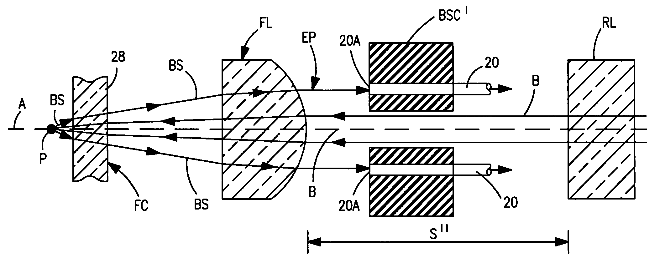
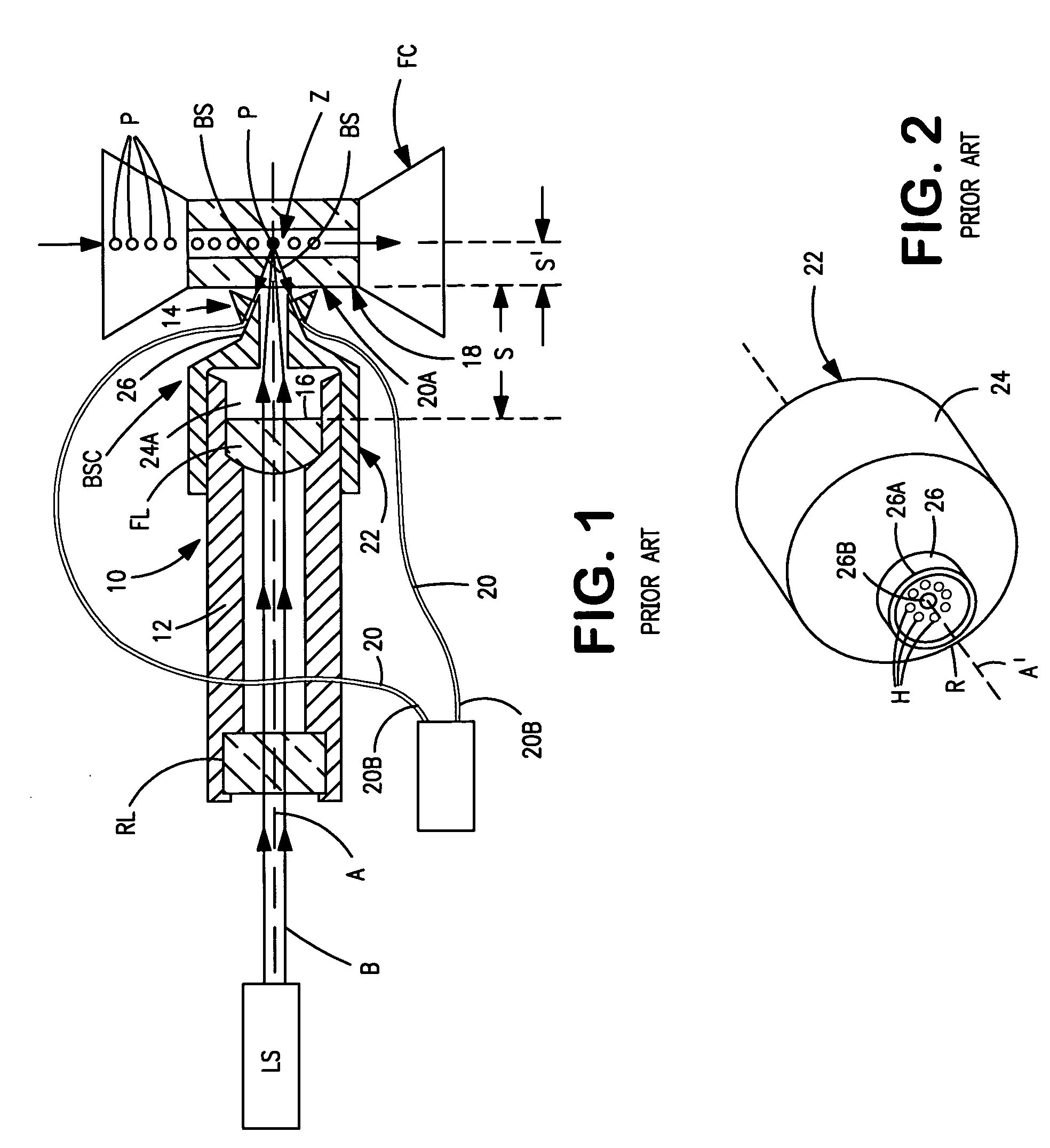
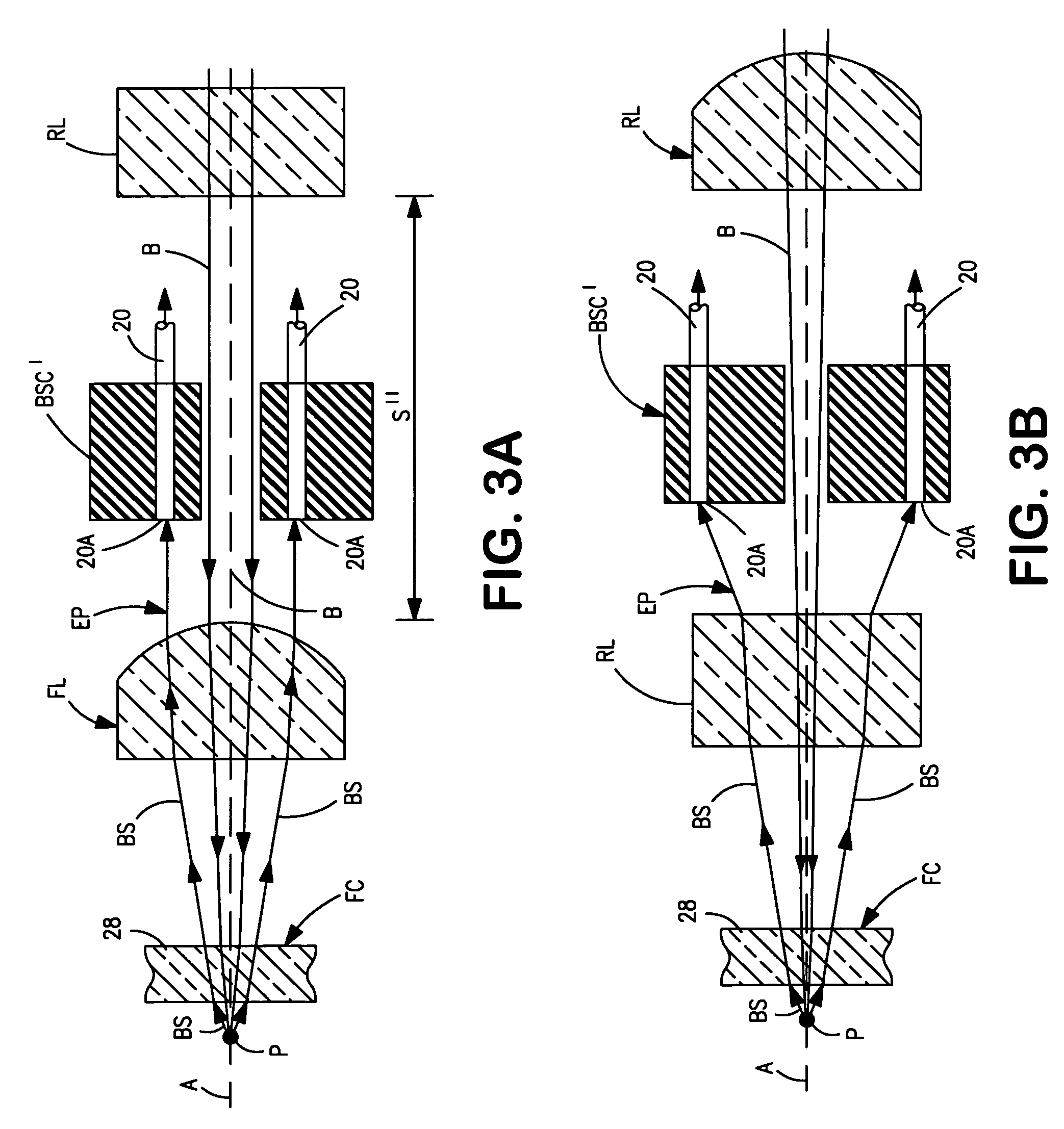
[0020]Referring now to the drawings, FIG. 1 schematically illustrates a conventional approach for collecting and detecting back-scattered light BS scattered by small particles P, such as blood cells, upon being irradiated by a focused “light” beam B while passing through the constricted interrogation zone Z of a transparent optical flow cell FC of the type commonly found in conventional flow cytometers. (Note, the word “light” is used herein in a broad sense to refer to electromagnetic radiation in general, not necessarily that found in the visible region of the electromagnetic spectrum. Typically, however, the radiation used in flow cytometers to irradiate particles and cells is found within the near-ultraviolet to the near-infrared region of the spectrum.) The stream of particles passing through the flow cell is maintained at or near the center of zone Z by a hydrodynamic focus flow scheme in which the stream is confined by a sheath liquid flowing through the flow cell simultaneou...
PUM
| Property | Measurement | Unit |
|---|---|---|
| focal length | aaaaa | aaaaa |
| focal length | aaaaa | aaaaa |
| diameter | aaaaa | aaaaa |
Abstract
Description
Claims
Application Information