Discrete polarization state rotatable compensator spectroscopic ellipsometer system, and method of calibration

a compensator and polarization state technology, applied in the field of ellipsometer and combined reflectometer/ellipsometer systems, can solve the problems that the other patents are not considered particularly relevant, and achieve the effects of reducing the number of sample systems, simplifying data acquisition, and greatly reducing system requirements

Inactive Publication Date: 2006-07-11
J A WOOLLAM CO
View PDF40 Cites 18 Cited by
  • Summary
  • Abstract
  • Description
  • Claims
  • Application Information

AI Technical Summary

Benefits of technology

[0104]It is also mentioned that said method of calibrating a spectroscopic ellipsometer system can require, in the step b. obtaining of at least one multi-dimensional data set(s) comprising intensity as a function of wavelength and a function of a plurality of discrete settings of said at least one means for discretely, sequentially, modifying a polarization state of a beam of electromagnetic radiation, the obtaining of data from at least as many sample systems as are utilized discrete settings of said at least one means for discretely, sequentially, modifying a polarization state of a beam of electromagnetic radiation provided by said source of polychromatic electromagnetic radiation. However, if characteristics of a means for discretely, sequentially, modifying a polarization state of a beam of electromagnetic radiation are parameterized, say as a function of wavelength, are expressed by equations with a minimized number of parameters therein, it is possible to reduce the number of sample systems which must be utilized.
[0105]The preferred embodiment of the present invention involves positioning input and output polarizer/analyzer system azimuthal angles at typical fixed,

Problems solved by technology

Said other Patents are not believed to be particularly relevant, however.
It is noted that if both the polarizer and analyzer are stat

Method used


Image

  • Discrete polarization state rotatable compensator spectroscopic ellipsometer system, and method of calibration
  • Discrete polarization state rotatable compensator spectroscopic ellipsometer system, and method of calibration
  • Discrete polarization state rotatable compensator spectroscopic ellipsometer system, and method of calibration

Examples


Embodiment Construction

[0171]FIGS. 1–3d and 4–13 show material previously disclosed in Co-Pending application Ser. No. 09 / 517,125, and discussion thereof is repeated herein to provide full disclosure and background for introducing material which is new herewithin. FIGS. 3e–3P demonstrate Compensators for application in the present invention, and FIGS. 14–16 show Retardation vs. Wavelength for Compensator designs which are Pseudo-Achromatic.

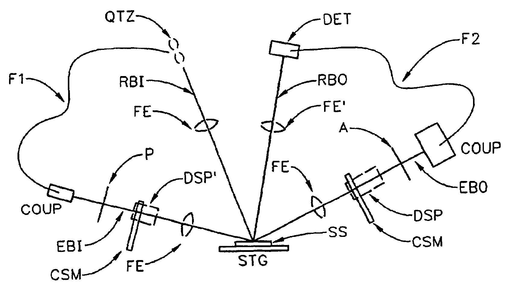
[0172]Turning now to FIG. 1, there is shown a spectroscopic ellipsometer system configuration. Shown are a source of polychromatic electromagnetic radiation (QTH), (eg. a quartz-halogen-lamp), a polarizer (P) a stage for supporting a sample system (STG) with a sample system (SS) present thereupon, a means (DSP) for discretely, sequentially, modifying a polarization state of a beam of electromagnetic radiation provided by said source of polychromatic electromagnetic radiation through a plurality of polarization states by passage therethrough, an analyzer (A), and a detec...


PUM


Abstract

Disclosed are spectroscopic ellipsometer and combined spectroscopic reflectometer/ellipsometer systems. The spectroscopic ellipsometer system portion includes polarizer and analyzer elements which remain fixed in position during data acquisition, and a step-wise rotatable compensator electromagnetic beam transmitting means, which serves to enable imposing a plurality of sequentially discrete, rather than continuously varying, polarization states on said beam of electromagnetic radiation. Further disclosed is a calibration procedure for said spectroscopic ellipsometer system portion of the invention which involves the gathering of, for each of a plurality of ellipsometrically distinct sample systems, spectroscopic data at a sequential plurality of discrete electromagnetic radiation beam polarization states, combined with providing of a mathematical model of the spectroscopic ellipsometer system and application of a mathematical regression procedure.

Description

[0001]This application is a Continuation-In-Part of Provisional Application Ser. No. 60 / 229,755 filed Sep. 5, 2000. This Application is also a Continuation-in-Part of application Ser. No. 09 / 517,125 filed Feb. 29, 2000, now abandoned, and of application Ser. No. 09 / 246,888 filed Feb. 8, 1999 now U.S. Pat. No. 6,084,675. Further, via the Ser. No. 09 / 246,888 Application, this application is a Continuation-In-Part of application Ser. No. 08 / 912,211 filed Aug. 15, 1997, (now U.S. Pat. No. 5,872,630), which was a CIP from application Ser. No. 08 / 530,892 filed Sep. 20, 1995, (now U.S. Pat. No. 5,666,201); and is a CIP of application Ser. No. 08 / 618,820 filed Mar. 20, 1996, (now U.S. Pat. No. 5,706,212). This Application is further a CIP of Co-Pending application Ser. Nos. 09 / 225,118; 09 / 223,822; 09 / 232,257; 09 / 225,371; 09 / 225,076 each filed Jan. 19, 1999 which Applications depend from application Ser. No. 08 / 997,311 filed Dec. 23, 1997, now U.S. Pat. No. 5,946,098. In addition, priority i...

Claims


Application Information

Patent Timeline
IPC IPC(8): G01J4/00
CPCG01N21/211G01N21/274G01N2021/213
Inventor JOHS, BLAINE D.HERZINGER, CRAIG M.GREEN, STEVEN E.HALE, JEFFREY S.
Owner J A WOOLLAM CO
Why Eureka
Try Eureka