Image inspection device

a technology of image inspection and output image, which is applied in the field of image inspection devices, can solve the problems of complex comparison processing and inability to completely automate inspection of output images, and achieve the effect of simplifying inspection of output images

Inactive Publication Date: 2006-07-11
FUJIFILM BUSINESS INNOVATION CORP
View PDF12 Cites 35 Cited by
  • Summary
  • Abstract
  • Description
  • Claims
  • Application Information

AI Technical Summary

Benefits of technology

[0009]The present invention is provided to solve the above-described problems, and an object of the present inventio

Problems solved by technology

Thus, there is a problem in that inspection of the output image cannot be completely

Method used


Image

  • Image inspection device
  • Image inspection device
  • Image inspection device

Examples


processing example 1

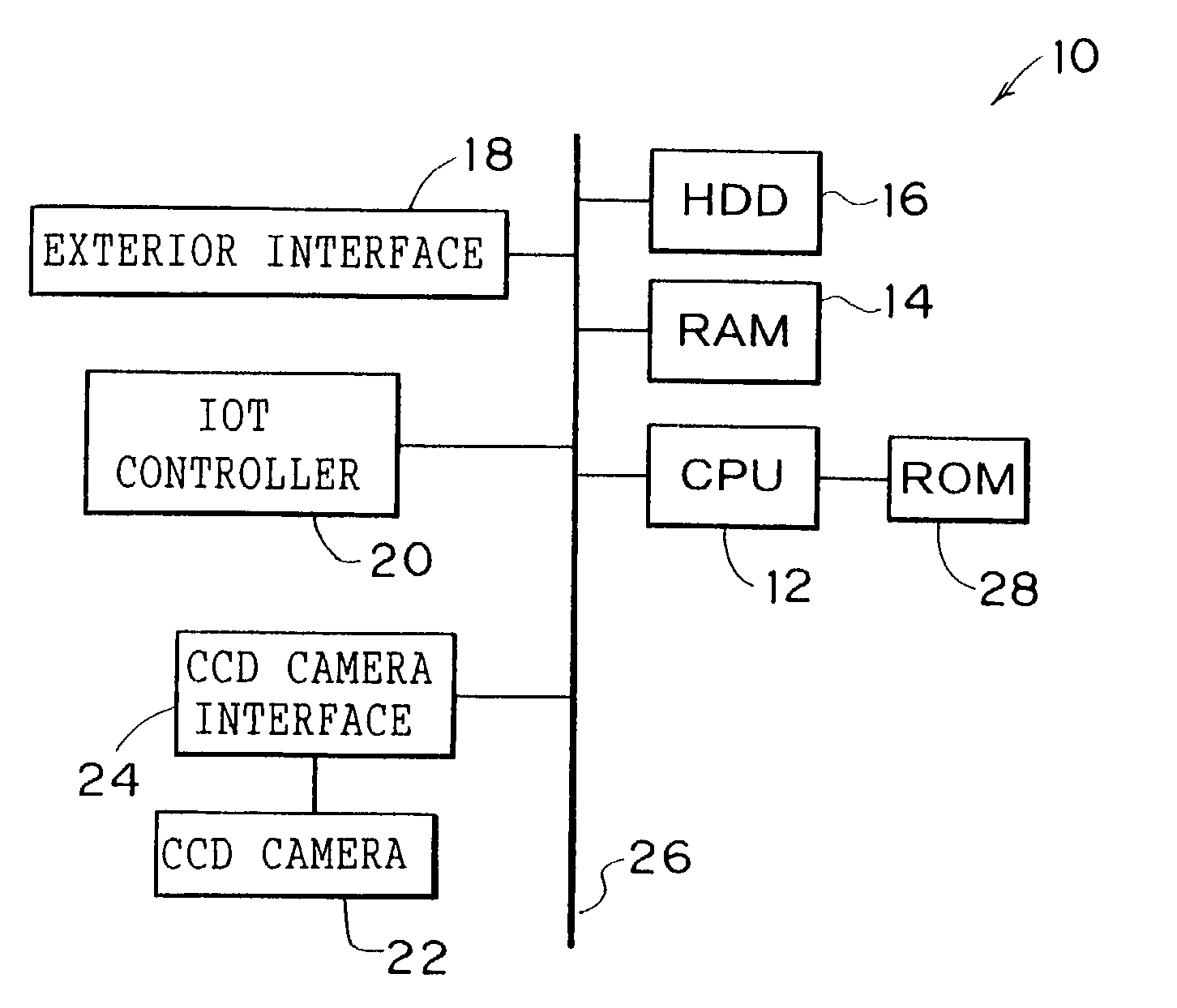
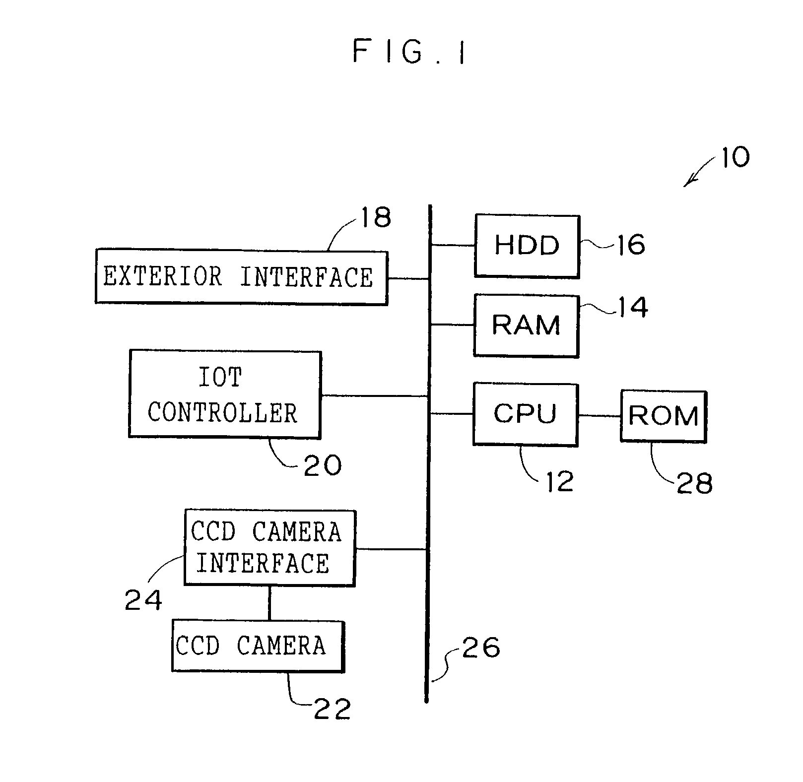
[0045]FIG. 3 shows a control routine of the laser printer 50, which is executed by the CPU 12. As shown in FIG. 3, in a waiting state of print processing, control periodically proceeds from step 100 to steps 102 and 104 at predetermined intervals, and an image inspection feasibility determination process shown in FIG. 4 is executed.

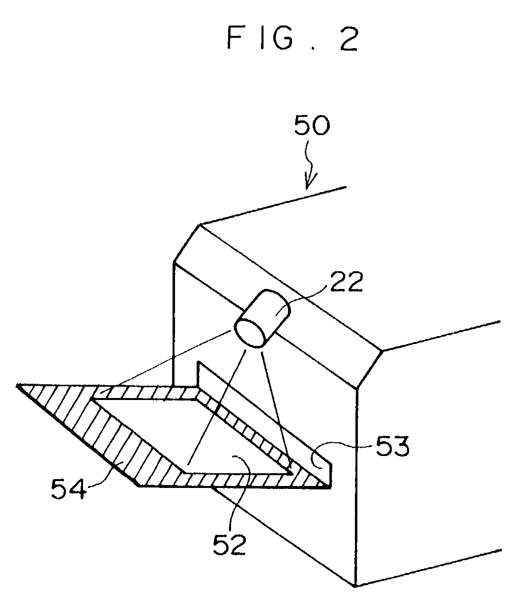
[0046]As shown in FIG. 4, in the image inspection feasibility determination process, photographing instruction is sent to the CCD camera 22 in a step 120. The CCD camera 22 photographs the paper discharge tray 54 in accordance with these instruction. The image data photographed by the CCD camera 22 is converted to digital signals at the interface circuit 24 which interfaces with the CCD camera 22, and is stored at the RAM 14.

[0047]In a subsequent step 122, the photographed (captured) image data acquired in accordance with the photographing instruction in step 120 is compared with image data for the tray, which has been stored in the RAM 14 in advance. In ...

processing example 2

[0073]In processing example 1, an example of a case in which, in the image inspection processing, the shape processing is applied to the captured image data for comparison of the captured image data and the original image data has been explained. However, the shape processing may be applied to the original image data side. FIG. 8 shows a flowchart of an image inspection process in such a case. In FIG. 8, processing that is the same as in FIG. 6 is given the same step numbers, and details thereof will not be explained.

[0074]As shown in FIG. 8, optical distortion correction is applied to the captured image data in step 166. Then control passes to step 170, the paper region is specified, cropping to the specified paper region is carried out, and captured image data for comparison is stored at the RAM 14. That is, the captured image data for comparison is cropped with the paper region still in a trapezoid shape.

[0075]Resolution conversion processing is applied to the original image data...

processing example 3

[0077]In processing example 1, detection of image defects is carried out by image inspection processing for only the first page of print processing results in a print job, and then defect judgement is carried out. However, as described above, detection of image defects is performed by difference processing after correction has been applied to both captured image data and original image data. Therefore, there is a possibility that erroneous judgements may occur, due to threshold values used at the time of defect judgement, correction errors and the like. Accordingly, defect judgement may be carried out not by detecting image defects on just the first page of print processing results, but by carrying out defect judgement by image inspection processing of print processing results of a plurality of pages.

[0078]FIG. 9 shows a flowchart of print control processing in a case in which, as an example, image defect detection is carried out for all print processing results in one print job, an...


PUM


Abstract

An image inspection device to automate and simplify inspection of an output image. A paper discharge tray of a printer is a different color from paper. A CCD camera is disposed above a paper discharge portion of the printer, at which paper is discharged, and can capture the whole upper face of the paper discharge tray. When, directly after a state in which there is no paper on the paper discharge tray, a print job is received and a first print-processed sheet is outputted to the paper discharge tray, a CPU controls the CCD camera to capture the paper discharge tray in this state. Captured image data including the paper is acquired, corrections are applied to the captured image data and to original image data by image processing, and image characteristics thereof are made substantially the same. Thereafter, the outputted image is inspected by comparison of the two data sets.

Description

BACKGROUND OF THE INVENTION[0001]1. Field of the Invention[0002]The present invention relates to an image inspection device, and particularly relates to an image inspection device to be used in an image output device which outputs an image recording medium, on which an image has been recorded on the basis of image data, to an output tray.[0003]2. Description of the Related Art[0004]Conventionally, in order to maintain image quality of print in a printing apparatus, inspections of print results (outputted images) has been performed. In recent years, demands for higher image quality, even in laser beam printers and digital copying devices equipped with laser beam printers, have risen, and maintenance in accordance with inspection of outputted images has been deemed to be necessary. Further, in order to lower costs, automation and remote operation of maintenance works have been called for.[0005]Japanese Patent Application Laid-Open (JP-A) No. 8-190630 proposes a technique for automatic...

Claims


Application Information

Patent Timeline
IPC IPC(8): G06K9/00G03G15/00G03G21/00G06T1/00H04N1/00H04N1/38H04N1/387
CPCH04N1/00002H04N1/00015H04N1/00037H04N1/387H04N1/0005H04N1/38H04N1/00047
Inventor MIYAKE, HIROYUKIYAMADA, NORIKAZUSATONAGA, TETSUICHINAKAGAWA, EIGOUWATOKO, KOKI
Owner FUJIFILM BUSINESS INNOVATION CORP
Why Eureka
Try Eureka