
System and method for performing a hardware-in-the-loop simulation using a plurality of graphical programs that share a single graphical user interface

a hardware-in-the-loop simulation and user interface technology, applied in the field of graphical programming, can solve the problems of inability to test the control unit with the real physical system, inability to perform real-time simulation, and inability to meet the requirements of the real-time physical system

Active Publication Date: 2006-07-11
NATIONAL INSTRUMENTS
View PDF6 Cites 37 Cited by
  • Summary
  • Abstract
  • Description
  • Claims
  • Application Information

AI Technical Summary

Benefits of technology

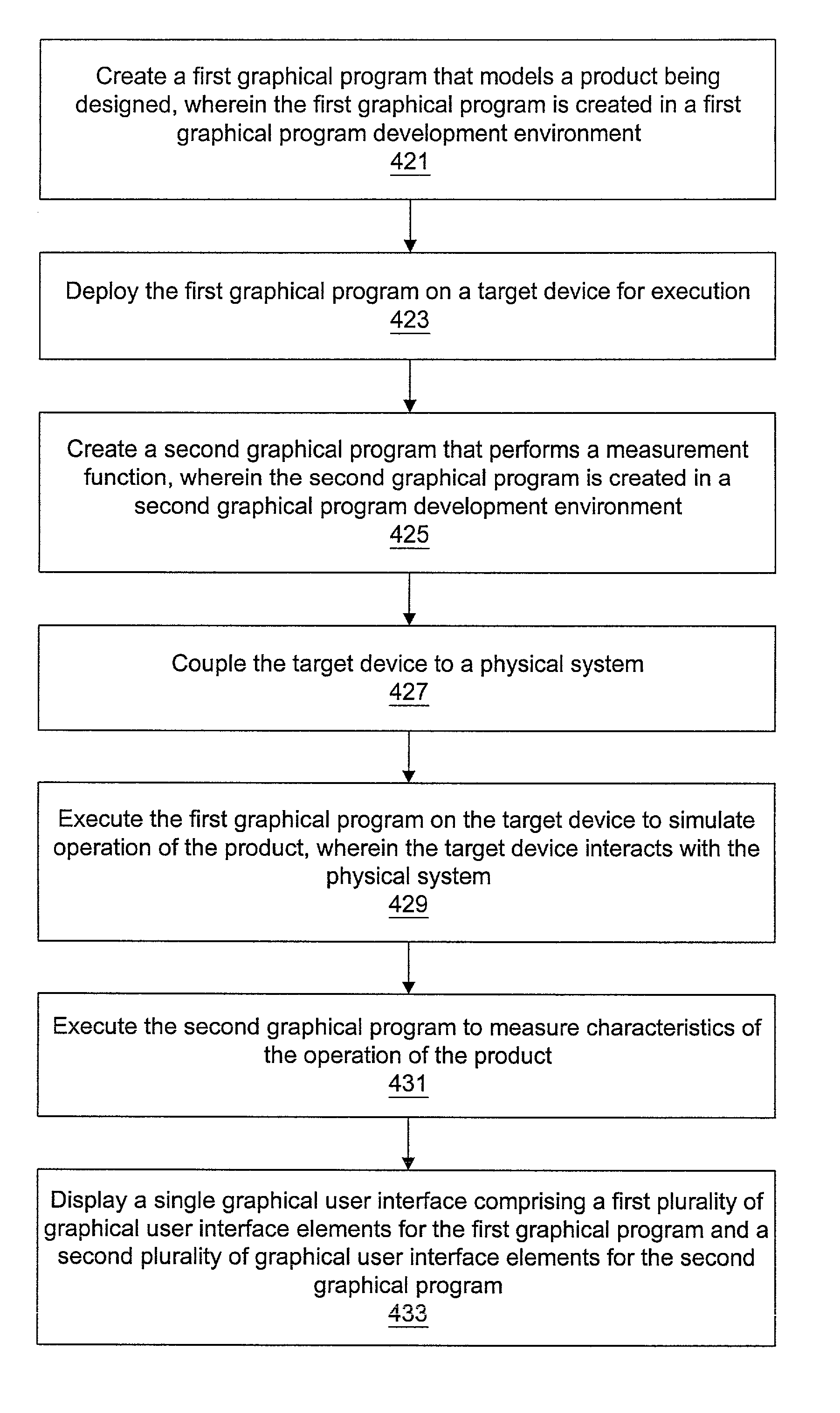
The patent describes a system and method for performing hardware-in-the-loop simulations using multiple graphical programs that share a single user interface. This allows for the testing of control units designed to control physical systems without the need for expensive or dangerous real-life testing. The system includes a computer system running a first graphical program that simulates the physical system, while a control unit is connected to the computer system and interacts with it. A second graphical program is used to measure the operation of the control unit. The system also includes a single user interface that displays the graphical user interface elements for both programs. The technical effect of this invention is the ability to efficiently and safely test control units designed to control physical systems.

Problems solved by technology

It may be impractical to test the control unit with the real physical system the control unit is designed to control.
For example, the tests may be too expensive, too dangerous, or impossible, e.g., the real physical system may not exist yet.

Method used


Image

  • System and method for performing a hardware-in-the-loop simulation using a plurality of graphical programs that share a single graphical user interface
  • System and method for performing a hardware-in-the-loop simulation using a plurality of graphical programs that share a single graphical user interface
  • System and method for performing a hardware-in-the-loop simulation using a plurality of graphical programs that share a single graphical user interface

Examples


Embodiment Construction

Incorporation by Reference

[0043]The following references are hereby incorporated by reference in their entirety as though fully and completely set forth herein.

[0044]U.S. Pat. No. 6,064,812 titled “System and Method for Developing Automation Clients Using a Graphical Data Flow Program,” issued on May 16, 2000.

[0045]U.S. Pat. No. 6,102,965 titled “System and Method for Providing Client / Server Access to Graphical Programs,” issued on Aug. 15, 2000.

[0046]U.S. Pat. No. 6,173,438 titled “Embedded Graphical Programming System” filed Aug. 18, 1997.

[0047]U.S. Pat. No. 6,219,628 titled “System and Method for Configuring an Instrument to Perform Measurement Functions Utilizing Conversion of Graphical Programs into Hardware Implementations,” filed Aug. 18, 1997.

[0048]U.S. patent application Ser. No. 09 / 136,123 titled “System and Method for Accessing Object Capabilities in a Graphical Program,” filed Aug. 18, 1998.

[0049]U.S. patent application Ser. No. 09 / 518,492 titled “System and Method for P...


PUM


Abstract

A system and method for performing a hardware-in-the-loop simulation using a plurality of graphical programs that share a single graphical user interface. A first graphical program that models a physical system may be created. The first graphical program may be deployed on a first computer system for execution. A second graphical program that performs a measurement function may be created. A control unit may be coupled to the first computer system. The first graphical program may be executed on the first computer system to simulate operation of the physical system, wherein the control unit interacts with the first computer system. The second graphical program may be executed to measure characteristics of the operation of the control unit. A single graphical user interface comprising a first one or more graphical user interface elements for the first graphical program and a second one or more graphical user interface elements for the second graphical program may be displayed.

Description

FIELD OF THE INVENTION[0001]The present invention relates to the field of graphical programming. In particular, the invention relates to a system and method for performing a hardware-in-the-loop simulation using a plurality of graphical programs that share a single graphical user interface.DESCRIPTION OF THE RELATED ART[0002]Traditionally, high level text-based programming languages have been used by programmers in writing application programs. Many different high level programming languages exist, including BASIC, C, Java, FORTRAN, Pascal, COBOL, ADA, APL, etc. Programs written in these high level languages are translated to the machine language level by translators known as compilers or interpreters. The high level programming languages in this level, as well as the assembly language level, are referred to herein as text-based programming environments.[0003]Increasingly, computers are required to be used and programmed by those who are not highly trained in computer programming te...

Claims


Application Information

Patent Timeline
Patent Type & Authority Patents(United States)
IPC IPC(8): G06G7/48G06F9/44
CPCG06F9/4443G06F9/451
Inventor SANTORI, MIKELIMROTH, JOHN
Owner NATIONAL INSTRUMENTS
Learn More