
Method for successive placement based refinement of a generalized cost function

a cost function and generalized technology, applied in the field of electronic design automation, can solve the problems of increasing the difficulty of simultaneous optimization of the cost function, increasing the difficulty of achieving optimal placement, and extra wire length, so as to improve the quality of the results achieved at the look ahead poin

Inactive Publication Date: 2006-07-11
INT BUSINESS MASCH CORP
View PDF20 Cites 24 Cited by
  • Summary
  • Abstract
  • Description
  • Claims
  • Application Information

AI Technical Summary

Benefits of technology

[0044]In another aspect of the invention, there is provided a method for optimizing the placement of a plurality of cells on a VLSI chip that includes the steps of: a) subdividing the plurality of cells into partitions by performing a sequence of cuts; b) iteratively managing the sequence of cuts to perform a look ahead operation; c) returning to the cut from where the look ahead operation was initiated by comparing the original placement with the cut provided by the look ahead operation; and d) altering the priority of the placement to ensure that the quality of the results achieved at the look ahead point is improved.

Problems solved by technology

Simultaneous optimization of the cost functions is difficult in view of certain cost functions competing against one another.
By way of example, better timing may require extra wire length, which is in direct conflict with the goal of minimizing the wire length.
In addition to internal cost function conflicts there are also other important optimizations such as timing, power, and signal integrity that are not easily visible to a native placement algorithm.
For these reasons, it becomes more difficult to achieve the optimal placement.
A drawback of this approach is that they do not allow changes in the global qualities of the placement to be applied to the optimization.
These approaches are limited in their ability to modify the global placement in order to achieve optimization.

Method used


Image

  • Method for successive placement based refinement of a generalized cost function
  • Method for successive placement based refinement of a generalized cost function
  • Method for successive placement based refinement of a generalized cost function

Examples


Embodiment Construction

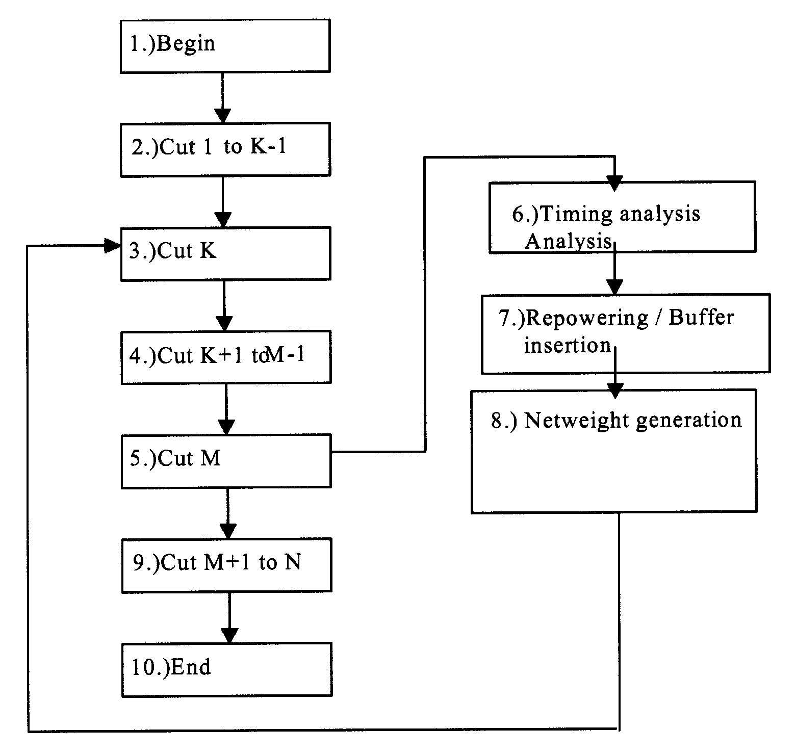
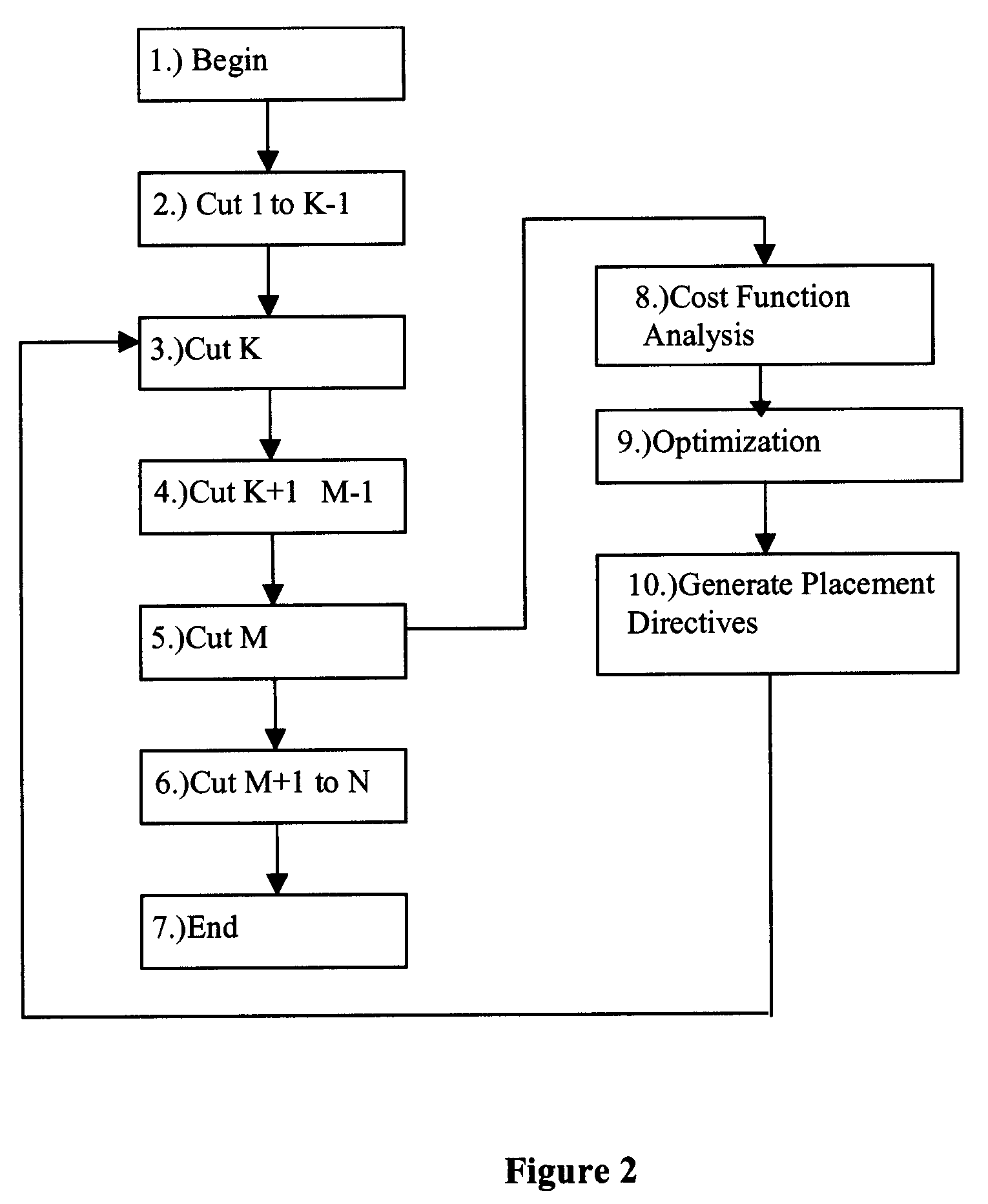
[0054]Referring now to FIG. 2, there is shown a flowchart illustrating the method steps for performing the placement optimization relative to a given cost function, in accordance dance to the present invention.

[0055]The inventive method uses a successive partition placement flow iteratively. In step 2 of the iteration, the flow begins at cut 1 and ends at cut M (step 5). Cut M is determined by the algorithm to be a value such that M2 is evaluated using predefined cost metrics. Based on the evaluation of the cost metrics, directive inputs to placement are specified. This evaluation and directive generation step is shown in steps 8, 9, and 10.

[0056]Still referring to FIG. 2, steps 3–5 perform a placement from cut K (step 3) through M (step 5). When the iteration M>K>1 is reached, K is selected so that the starting point of the second iteration captures some global qualities of the initial placement. Likewise, M is computed in accordance with the desired level of placement approximatio...


PUM


Abstract

A generalized method for optimizing the global placement of a VLSI chip across multiple cost metrics, such as total wire length, timing, congestion, and signal integrity is described. The method relies upon a “look ahead” technique, combined with any generic cost function that can be used to set placement directives. These placement directives include net weights and cell spreading. The method of performing the placement involves the iterative reuse of the process of successive partitioning. This iterative reuse establishes the capability of looking ahead to determine what is to happen. Based on the look ahead, it is possible to evaluate the qualities of the placement about to be generated. The method proceeds through the placement from while maintaining the current state of the placement along with the look-ahead state of the placement. Directives are generated and modified in order that the next steps applied to the current state of the placement will cause it to change to achieve an ultimate higher quality final output.

Description

BACKGROUND OF INVENTION[0001]The invention is generally related to the field of Electronic Design Automation as applied to the design of semiconductor chips, and more specifically, to a method for optimizing the placement of cells on the chip.[0002]Placement has been an integral part of any VLSI chip design for many decades. Several approaches exist in the art for solving the placement problem. One of the most successful ones, known as partitioning, has been widely described in the technical literature, as for instance, by R. S. Tsay, E. S. Kuh and C. P. Hsu, “PROUD: a Sea-of-Gates Placement Algorithm”, published in IEEE Design & Test of Computers, Vol. 5, December 1988; by J. M. Kleinhans, G. Sigl and F. Johannes; “Gordian: A New Global Optimization / Rectangle Dissection Method for Cell Placement”, published in the Proceedings of the International Conference on Computer-Aided Design, pp. 506–509, 1988; and by G. Sigl, K. Doll and F. Johannes, “Analytical Placement: A Linear or Quadr...

Claims


Application Information

Patent Timeline
Patent Type & Authority Patents(United States)
IPC IPC(8): G06F17/50
CPCG06F17/5072G06F2217/08G06F30/392G06F2111/06
Inventor REN, HAOXINGVILLARRUBIA, PAULKURZUM, ZAHI M.RAMJI, SHYAM
Owner INT BUSINESS MASCH CORP
Learn More