Active protection system

a technology of active protection and protection system, applied in the field of armaments, can solve the problems of increasing the reaction time of protective ammunition, radar on the turret, and the entire active protection system becoming “blind” and completely out of operation, and achieve the effect of improving the tactical and technical performance of the entire system

Inactive Publication Date: 2006-07-18
SHUMOV
View PDF9 Cites 25 Cited by
  • Summary
  • Abstract
  • Description
  • Claims
  • Application Information

AI Technical Summary

Benefits of technology

[0005]Accordingly, it is an object of the present invention to provide an active protective system which avoids the disadvantages of the prior art.
[0006]In accordance with the present invention an active protective system is proposed in which protective ammunition and devices for detection of high-speed and slow-speed incoming means are combined in a single autonomous unit, and such units are arranged around the perimeter of a tank and on its turret to substantially improve the tactical and technical performance of the system and its reliability.
[0015]The new features of the autonomous ammunition system in accordance with the present invention reside in implementing of each of the protective ammunition rounds firmly linked to the target detection device and to the means for moving protective ammunition out toward the target, in (electrical) connection both to the data and control system and especially in combining at least two protective ammunition rounds into a single autonomous unit which is located within the armored case. Such a design allows mounting of such units along the entire perimeter of the contour of the tank, and also on its turret, which improves tactical and technical performance of the entire system and its reliability.

Problems solved by technology

This system has the disadvantage in the existence of devices for detection of outside objects placed in the protected zone, which increases the reaction time for protective ammunition.
In particular the location of the radar on the turret is disadvantageous, since in case of getting hit by, for example small arms or shell-splinters, or mine-splinters, the entire active protection system actually becomes “blind” and will be completely out of operation.
Also, the arrangement of protective ammunition around the turret decreases the reliability and protective performance of the entire system, because their concentration at the turret area increases the likelihood of their destruction by splinters, high-caliber machine-gun bullets, etc.
The above described disadvantages reduce the reliability of this known active protection system.

Method used


Image

  • Active protection system
  • Active protection system
  • Active protection system

Examples


Embodiment Construction

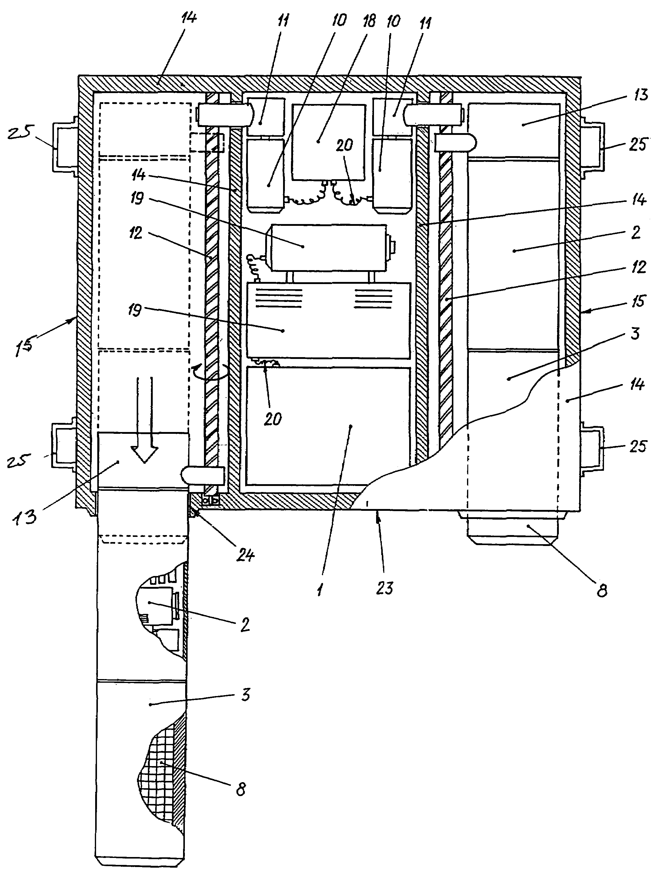
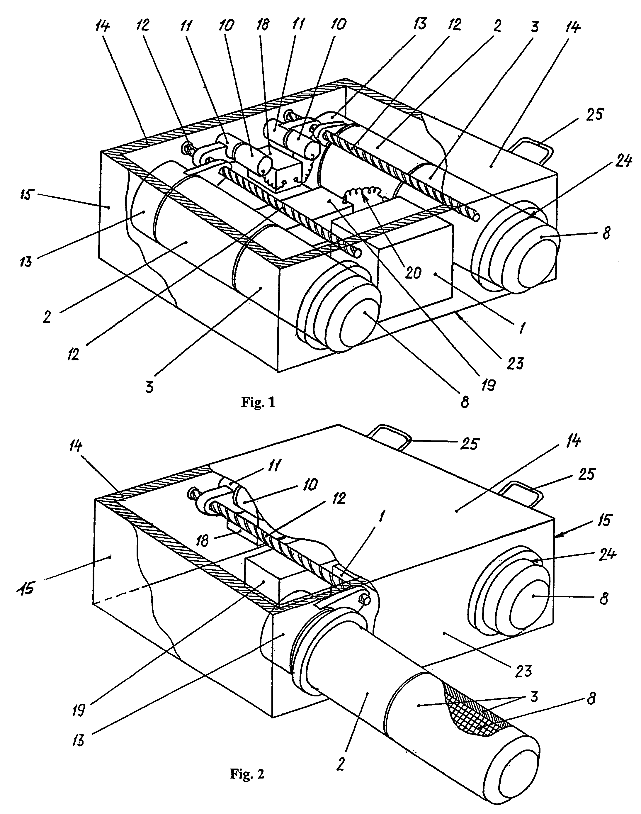
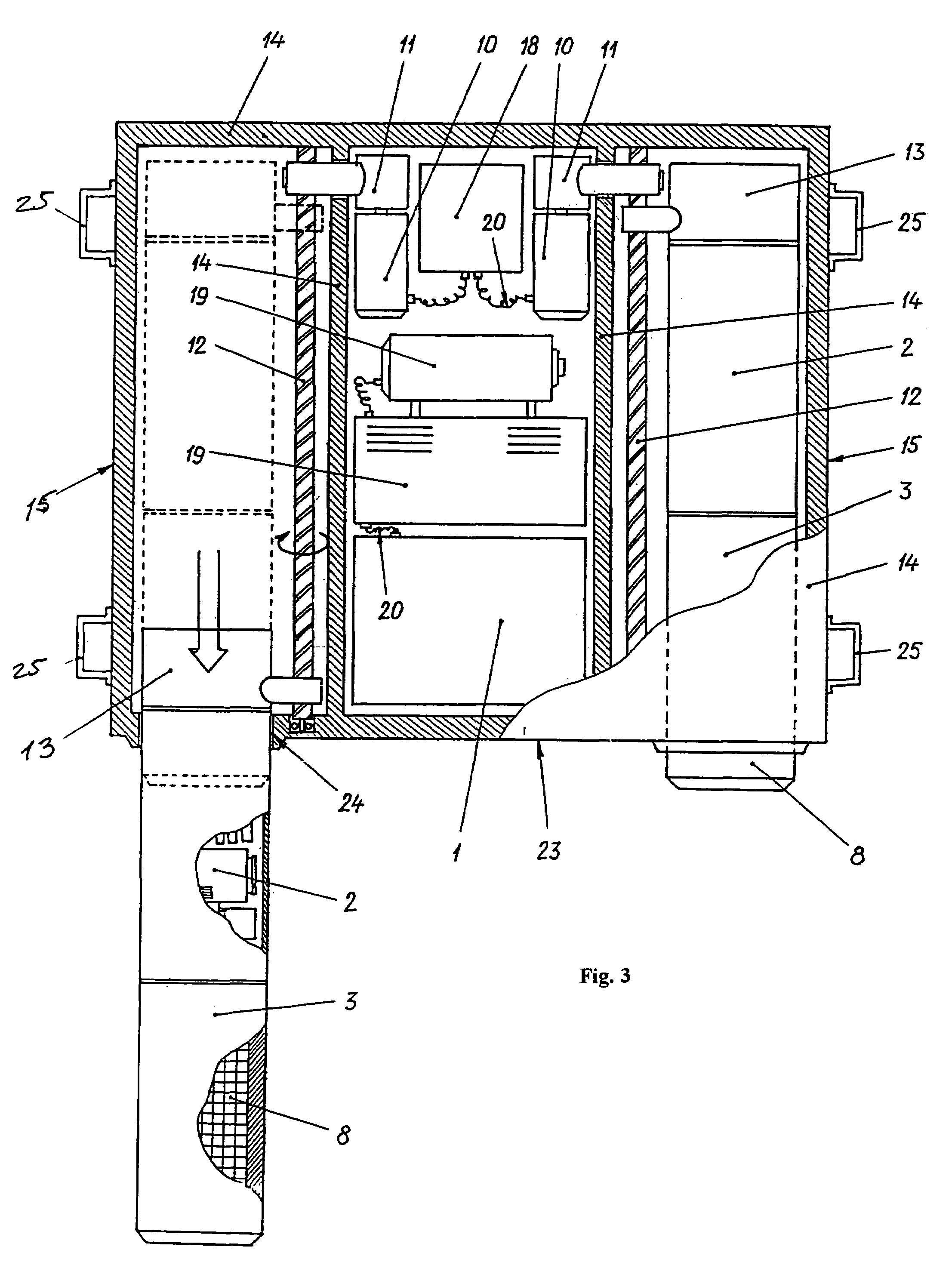
[0023]An active protection system in accordance with the present invention comprises a data and control system 1, a detection system 2, a target destruction system 3, a control panel 4, and a device 5 for blocking fire control circuits while hatches of an armored protected object 6 are open.

[0024]The detection system 2 can be formed for example as a radar. The control panel 4 is formed so that it can be placed within a fighting compartment 7 of the protected armored object 6, for example in a turret of a tank as shown in FIG. 5. The target destruction system 3 is formed as an interlinked protective ammunition 8 and a device moving out the protective ammunition 8 toward the incoming anti-tank means (the target). The protective ammunition 8 is firmly connected to the radar to form a unit as shown in FIGS. 1 and 3.

[0025]The device for moving out protective ammunition 8 toward the incoming antitank means 9 includes for example an electrical motor 10 with a reducer 11, a directing helica...


PUM


Abstract

A system of active protection system of objects has a central control panel, and at least one unit arrangeable on a protected object and including a target detection device, a protective ammunition connected with the target detection device, a device for moving the target detection device and the protective ammunition device, and a case accommodating the target detection device, the protective ammunition, and the moving out device, so that when the target detection device of the at least one unit detects a target, the ammunition of the at least one unit is moved out of the case and fired.

Description

BACKGROUND OF THE INVENTION[0001]The present invention relates to armaments, in particular to means for active protection of military equipment from high-speed destruction means, or in other words to active protection systems.[0002]Active protection systems are known in the art. In particular, there are already known active protective systems which use the effect of reciprocal (in relation to incoming destruction means) explosion. One of such active protective systems is disclosed in the French patent application no. 2676536. It includes at least one system of launching elements made of pipes, which house protective ammunition. The launching elements are arranged so that they create a protection zone in the form of arcs of a circle. The system has a protective ammunition launch control unit and means for detection of outside objects. The detection means include a system of detectors which are located within the controlling area and connected to the central control unit.[0003]This sy...

Claims


Application Information

Patent Timeline
Patent Type & Authority Patents(United States)
IPC IPC(8): F41H5/007F41H11/02
CPCF41H11/02F41H5/007
Inventor SHUMOV, SERGEI ALEKSANDROVICHKHITRYK, VASILIJ ONUFRIEVICHMEDVID, VLADIMIR STANISLAVOVICHPOYHINA, MARINA IVANOVNA
Owner SHUMOV
Why Eureka
Try Eureka