
Container with valve assembly for filling and dispensing substances, and apparatus and method for filling

a technology of container and valve, which is applied in the field of containers, can solve the problems of relatively complex and expensive process of sterile filling of medicament containers or dispensers, such as vials, and achieve the effect of improving the level of sterility assurance and cost reduction

Active Publication Date: 2006-07-18
DR PY INST LLC
View PDF137 Cites 81 Cited by
  • Summary
  • Abstract
  • Description
  • Claims
  • Application Information

AI Technical Summary

Benefits of technology

"The present invention is a container or dispenser for holding medications or other substances, such as a vial, with a valve assembly that can be opened and closed to control the passage of substances in and out of the container. The valve assembly includes a flexible valve member and a valve seat, and the valve member is movable between an open position and a closed position. The container or dispenser can be sterilized and then filled with a sterile substance through the valve assembly. The valve assembly is designed to form a fluid-tight seal when in the closed position. The invention allows for easy assembly, sterilization, and filling of containers and dispensers with medications or other substances."

Problems solved by technology

Sterile filling of medicament containers or dispensers, such as vials, is a relatively complex and expensive process.
Also, many current vial and stopper assemblies do not permit mechanical connection to a syringe such that the same vial can be used to provide multiple doses of medicaments or other substances contained therein.

Method used


Image

  • Container with valve assembly for filling and dispensing substances, and apparatus and method for filling
  • Container with valve assembly for filling and dispensing substances, and apparatus and method for filling
  • Container with valve assembly for filling and dispensing substances, and apparatus and method for filling

Examples


Embodiment Construction

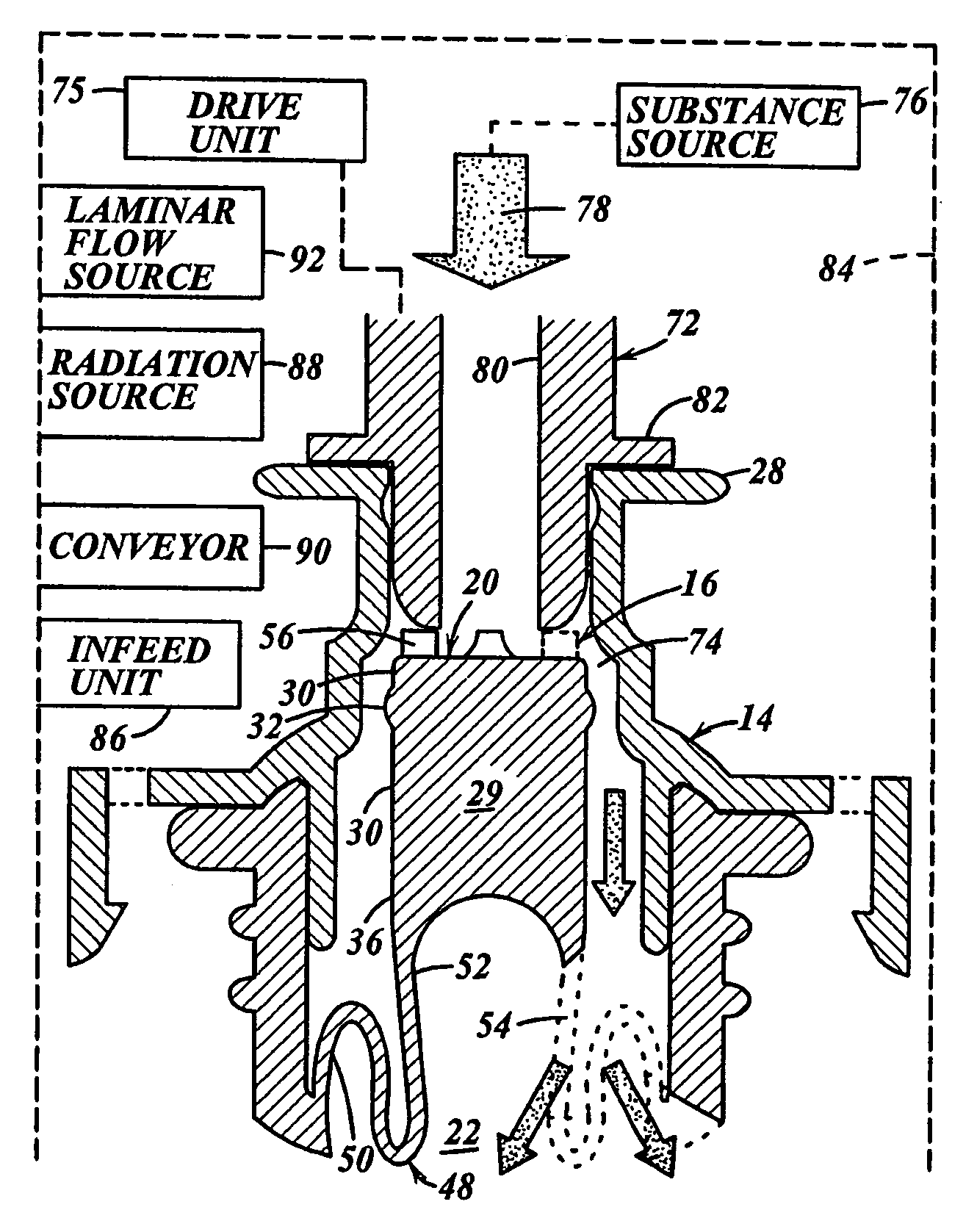
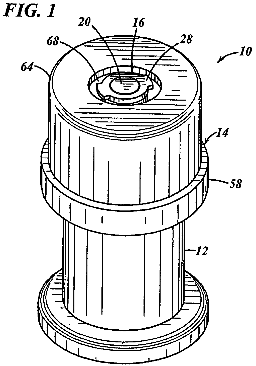
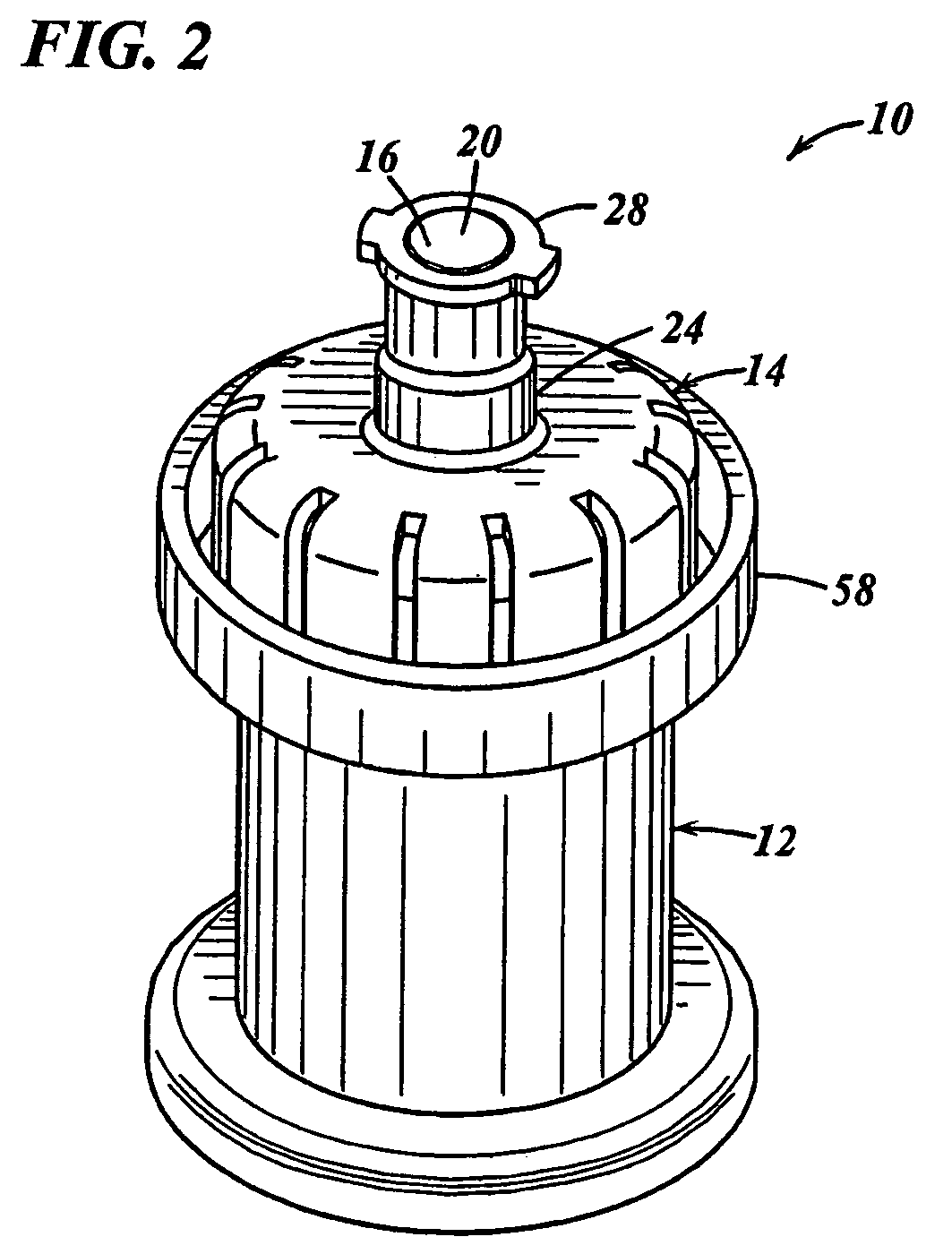
[0053]In FIG. 1 a vial assembly embodying the present invention is indicated generally by the reference numeral 10. The vial assembly 10 includes a body 12, a cap assembly 14 and a valve assembly 16 mounted within the cap assembly. As shown in FIGS. 4–8, the valve assembly 16 includes a valve seat 18 and a flexible valve member 20. The body 12 defines a chamber 22 coupled in fluid communication with the valve assembly 16. As described in further detail below, the flexible valve member 20 is movable between a closed position, as shown in FIGS. 4–7, wherein the flexible valve member 20 sealingly engages the valve seat 18 to form a fluid-tight seal therebetween and hermetically seal a substance contained within the chamber 22 within the vial, and an open position, as shown in FIGS. 8–10, wherein the valve member 20 is moved out of engagement with the valve seat 18 to define an opening therebetween and, in turn, permit the passage of substance through the valve assembly to both introduc...


PUM

PropertyMeasurementUnit
flexibleaaaaaaaaaa
energyaaaaaaaaaa
stored energyaaaaaaaaaa

Abstract

A vial has a body defining a chamber for receiving a substance therein; and a valve assembly coupled in fluid communication with the chamber and defining (i) an open position permitting at least one of (a) passage of the substance through the valve assembly and into the chamber for storing the substance in the chamber, and (b) passage of the substance out of the chamber for dispensing the substance therefrom; and (ii) a closed position forming a fluid-tight seal between the chamber and exterior of the container. A filling member engages a flexible valve member of the valve assembly to move the valve member between the closed and open positions to fill and seal the vial, respectively. A syringe is connectable to the vial. The valve assembly opens upon connecting the syringe to the vial to allow the substance within the vial to be withdrawn from the vial and into the syringe by actuating a plunger of the syringe, and the valve assembly closes upon disconnecting the vial and syringe to hermetically seal and store the substance remaining in the syringe for later use.

Description

CROSS-REFERENCE TO RELATED APPLICATIONS[0001]This application claims priority to U.S. Application Ser. No. 60 / 465,992, filed Apr. 28, 2003, titled “Container with Valve Assembly for Filing and Dispensing Substances, and Apparatus and Method for Filling”; to U.S. Application Ser. No. 60 / 469,677, filed May 12, 2003, titled “Dispenser and Apparatus and Method for Filling a Dispenser”; and U.S. Application Ser. No. 60 / 471,592, filed May 19, 2003, titled “Dispenser and Apparatus and Method for Filling a Dispenser”, the disclosures of which are hereby expressly incorporated by reference as part of the present disclosure.FIELD OF THE INVENTION[0002]The present invention relates to containers for storing and dispensing medicaments and other substances and to methods of filling such containers, and more particularly, to vials, dispensers, and other containers having valves for sealing substances within the containers and allowing the substances to be dispensed therefrom, and to apparatus and...

Claims


Application Information

Patent Timeline
Patent Type & Authority Patents(United States)
IPC IPC(8): B65B1/04A61J1/00A61J1/14A61J1/20A61J7/00A61J7/02B65D47/24
CPCA61J1/1412B65D47/248A61J1/18A61J1/2096B65B3/003B65B55/08A61J1/1475A61J2001/1425A61J2001/1431A61J2001/1468A61J2001/1481A61J2001/1487A61J2001/2037A61J2001/2041A61J2001/2055A61M2207/00A61J1/1425A61J1/1431A61J1/1468A61J1/1481A61J1/1487A61J1/2037A61J1/2041A61J1/2055
Inventor PY, DANIEL
Owner DR PY INST LLC
Learn More