Foot assembly of a clothes rack

a clothes rack and foot technology, applied in the direction of dismountable cabinets, curtain suspension devices, couplings, etc., can solve the problems of obsolete and necessary improvement of conventional clothes racks, and achieve the effect of improving the foot assembly and the required storage spa

Inactive Publication Date: 2006-07-18
WANG CHI CHUNG
View PDF11 Cites 42 Cited by
  • Summary
  • Abstract
  • Description
  • Claims
  • Application Information

AI Technical Summary

Benefits of technology

[0007]The primary objective of the present invention is to provide an improved foot assembly of a clothes rack. The foot assembly is able to be folded such that storage space required for the clothes rack is compact.

Problems solved by technology

Therefore, the conventional clothes rack is obsolete and improvement is required.

Method used


Image

  • Foot assembly of a clothes rack
  • Foot assembly of a clothes rack
  • Foot assembly of a clothes rack

Examples


Embodiment Construction

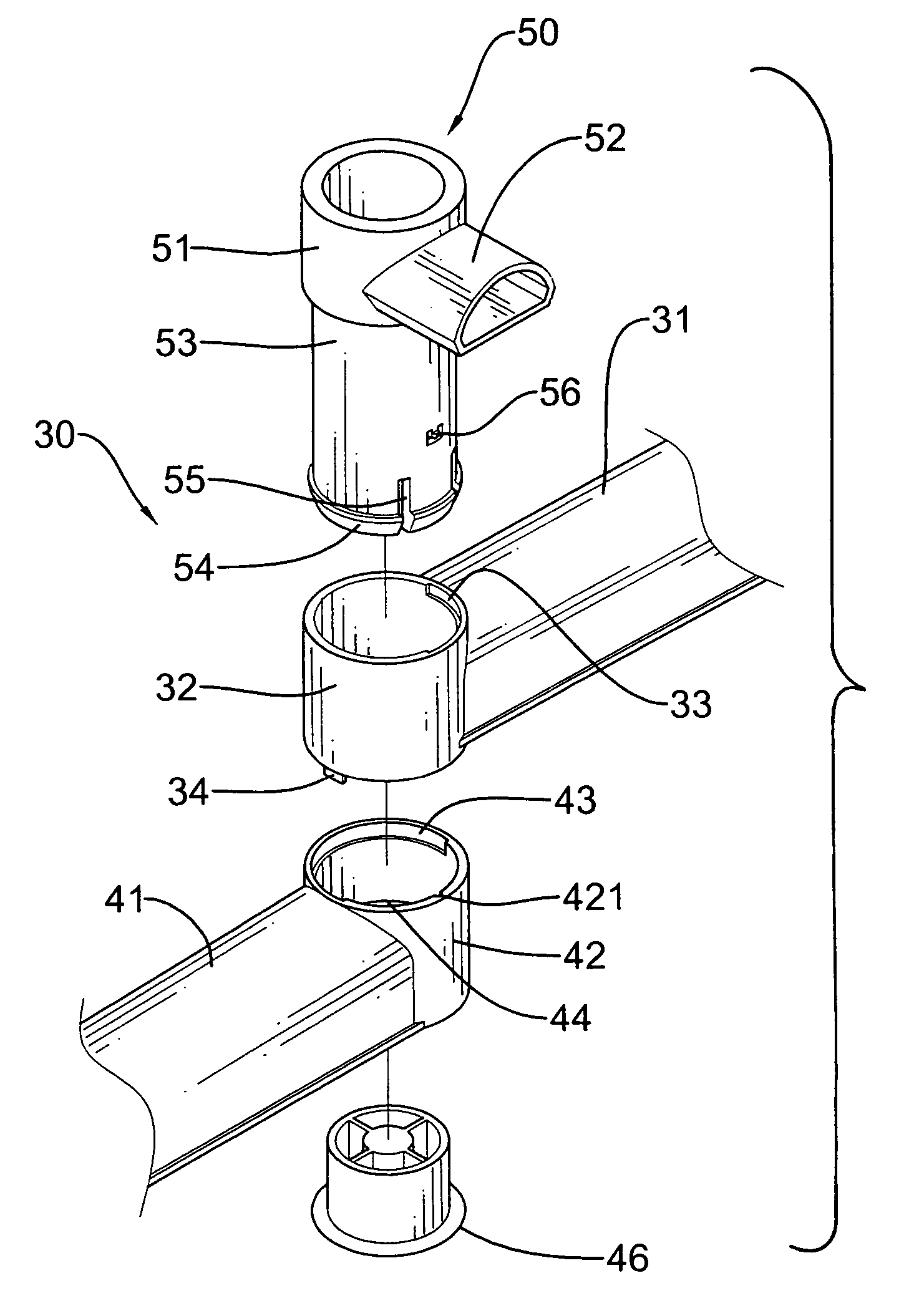
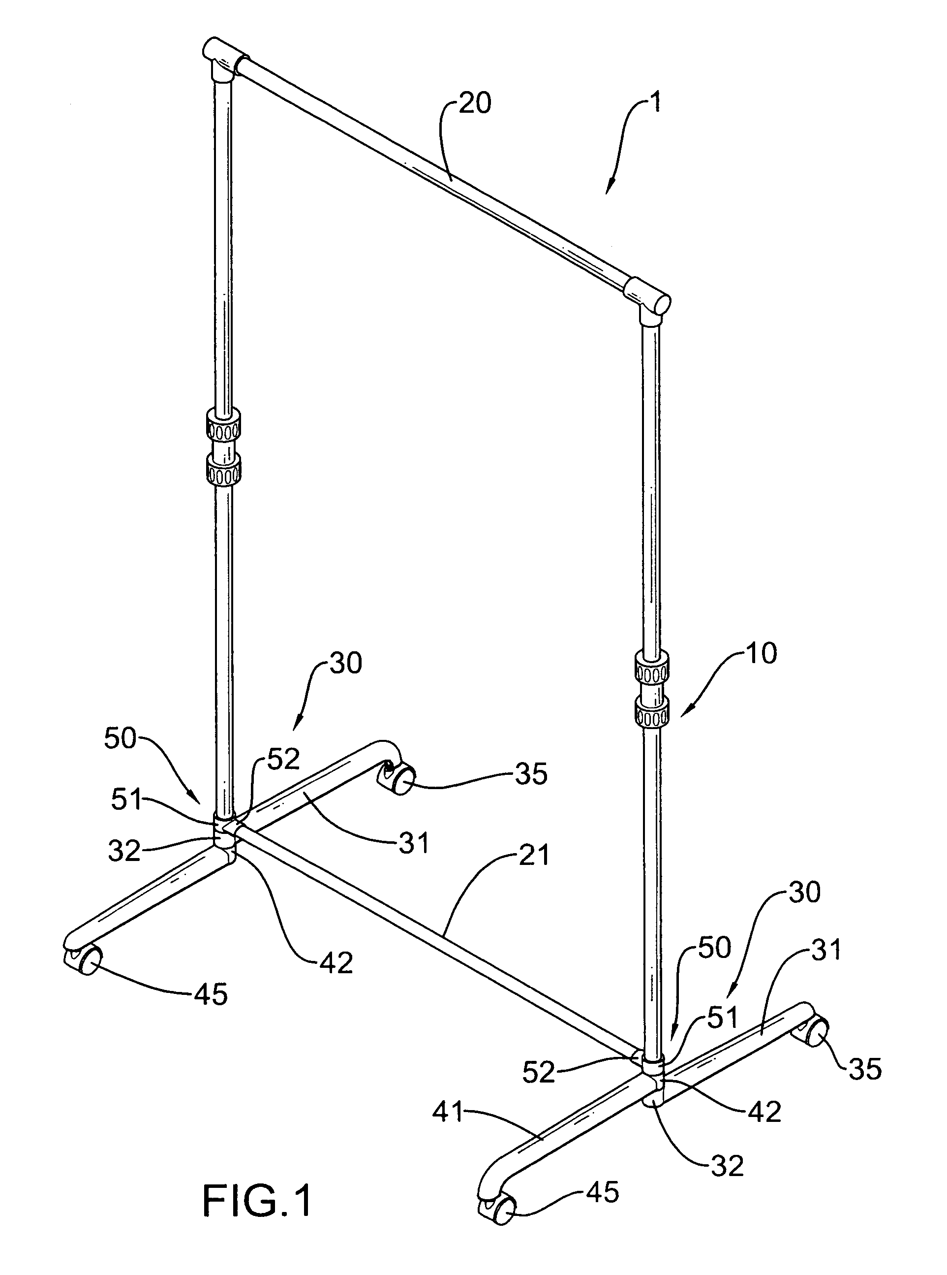
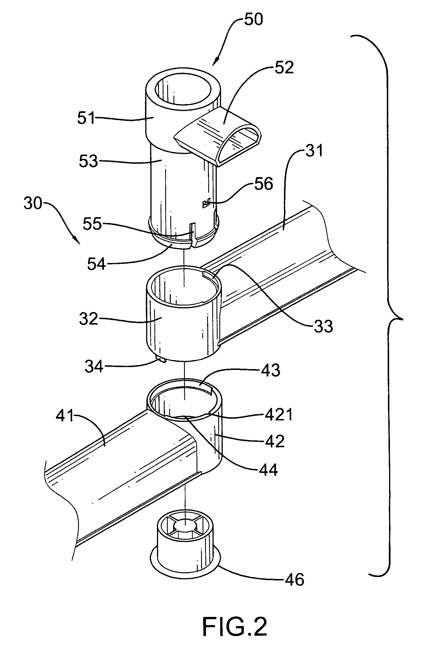
[0015]With reference to FIGS. 1 and 2, the clothes rack (1) in accordance with the present invention includes a top crossbar (20), a bottom crossbar (21) and two stanchions (10) respectively sandwiched between two opposite ends of the top crossbar (20) and the bottom crossbar (21). A foot assembly (30) is extended from a joint between the stanchion (10) and the bottom crossbar (21). The foot assembly (30) has a first leg (31) and a second leg (41) extending in a direction opposite to that of the first leg (31). A joint (50) is provided between the first leg (31) and the second leg (41).

[0016]The first leg (31) has a first ring (32) formed on a proximal end thereof and a first caster (35) rotatably mounted on a distal end thereof. The first leg (31) has a first limiting recess (33) defined in an inner face of the first ring (32) at a top opening and a first finger (34) extending from the inner face of the first ring (32) at a bottom opening. The second leg (41) has a second ring (42)...


PUM


Abstract

A foot assembly includes two first legs each having a first ring provided with a first limiting recess defined in an inner face of the first ring and a first finger extending from the inner face of the first ring, two second legs each having a second ring and a second limiting recess defined in an inner face of the second ring to movably receive therein the first finger of the first ring and two joints each having a third ring, a tube and a tubular extension formed on a bottom rim of the third ring to extend into the first ring and the second ring. The joint has a second finger to be movably received in the first limiting recess such that the first leg is able to align with the second leg for storage.

Description

BACKGROUND OF THE INVENTION[0001]1. Field of the Invention[0002]The present invention relates to a foot assembly, and more particularly to the foot assembly of a clothes rack to reduce occupied space when the rack is stored.[0003]2. Description of Related Art[0004]With reference to FIG. 6, a conventional clothes rack (6) is shown and has two opposite poles (60), a crossbar (70) securely connected to distal ends of the two poles (60) and two foot assemblies (80) respectively and securely connected to proximal ends of the two poles (60). Each foot assembly (80) has a first connector (81) and a second connector (82) formed on the foot assembly (80). The second connector (82) is to receive the proximal end of the pole (60) and the first connector (81) is to receive a distal end of a base bar (71). Two casters (83) are respectively mounted on opposed sides of each of the foot assemblies (80) to facilitate movement of the clothes rack (6). As shown in the drawing, it is noted that the foo...

Claims


Application Information

Patent Timeline
Patent Type & Authority Patents(United States)
IPC IPC(8): A47B46/00F16B12/40
CPCA47B91/02A47F5/137A47F7/24A47G25/0664Y10T403/32557Y10T403/32081Y10T403/606Y10T403/32591Y10T403/608Y10T403/32106
Inventor WANG, CHI-CHUNG
Owner WANG CHI CHUNG
Why Eureka
Try Eureka