
Pneumatically launched folding wing glider toy

a glider and pneumatic technology, applied in the field of toys, can solve the problems of limited altitude of gliders, and limited maximum altitude of gliders in parts

Inactive Publication Date: 2006-07-18
TBDUM LLC
View PDF25 Cites 12 Cited by
  • Summary
  • Abstract
  • Description
  • Claims
  • Application Information

AI Technical Summary

Benefits of technology

[0014]In another aspect of the invention, the wing sweep mechanism in a glider provides for a dampening effect allowing the wings to rotate forward upon sudden impact with the ground or other, objects preventing damage to the wing sweep mechanism and / or wings. The wings may be readjusted back into the proper operating orientation without damage to the wing sweep mechanism.

Problems solved by technology

Such gliders have been limited in terms of altitude due to the traditional means used to launch the glider, as well as the drag forces acting against the wings of the glider during its ascent.
For example, as to conventional gliders launched by a sling shot mechanism, the maximum altitude of the glider is limited in part by the strength of the rubber band or similar elastic member comprising the launching mechanism.
As to gliders launched by a user throwing the glider, the maximum altitude of the glider is limited in part by the strength of the thrower.
Additionally, conventional glider launching mechanisms typically lack an orientation-sensitive safety feature.
This presents a potential safety hazard in that a conventional glider may be launched directly at a person.
Damage to the glider may also result from the glider being launched in an improper direction.
While a parachute is effective in slowing a rocket's descent, it does not provide the visual stimulation provided by a glider.
In addition, the substantially vertical flight path of a rocket is not as visually stimulating as the relatively more arcuate flight path of a glider.
This produces the undesirable result of having to re-pump the launching mechanism for another launch attempt.

Method used


Image

  • Pneumatically launched folding wing glider toy
  • Pneumatically launched folding wing glider toy
  • Pneumatically launched folding wing glider toy

Examples


Embodiment Construction

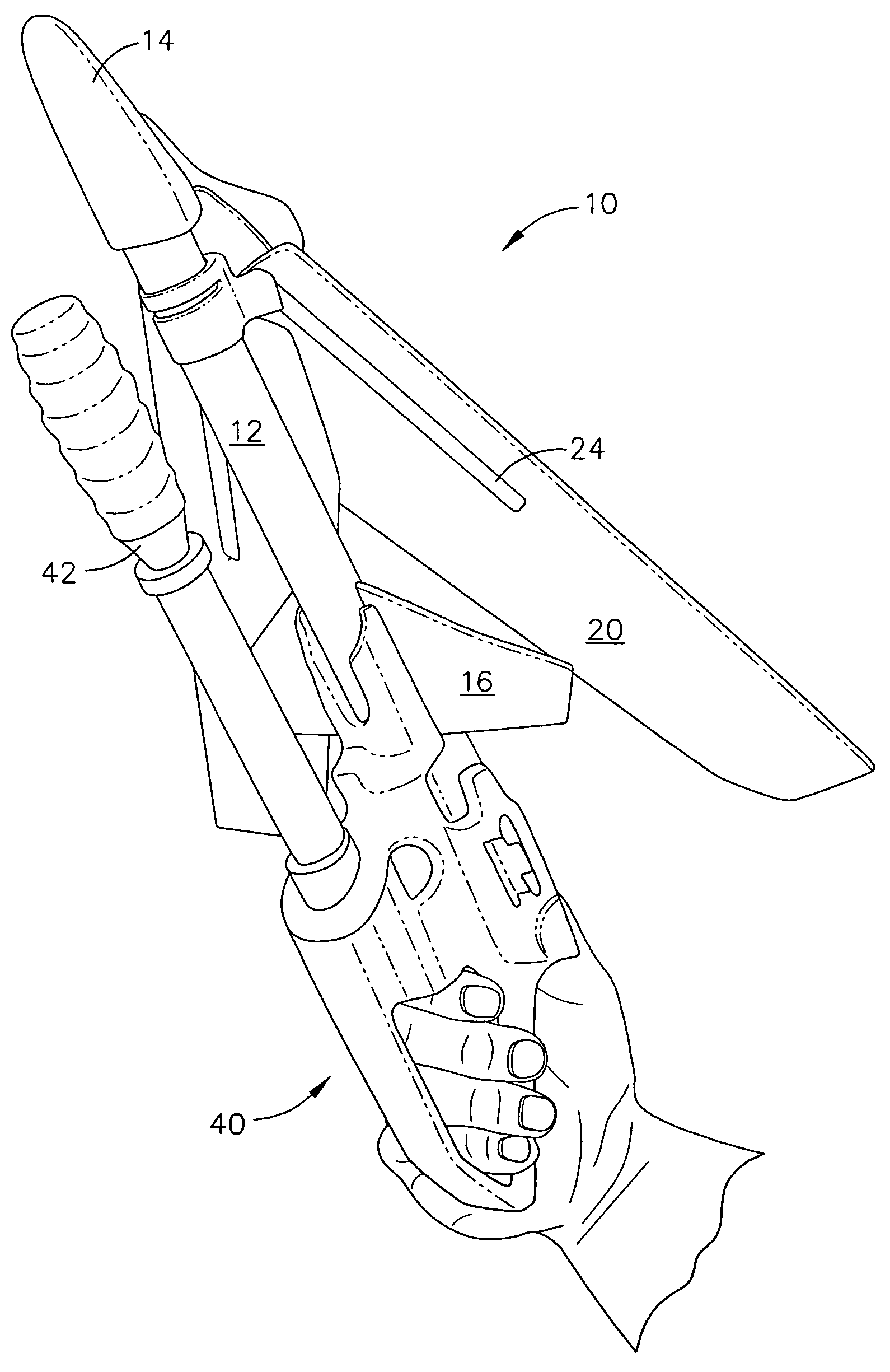
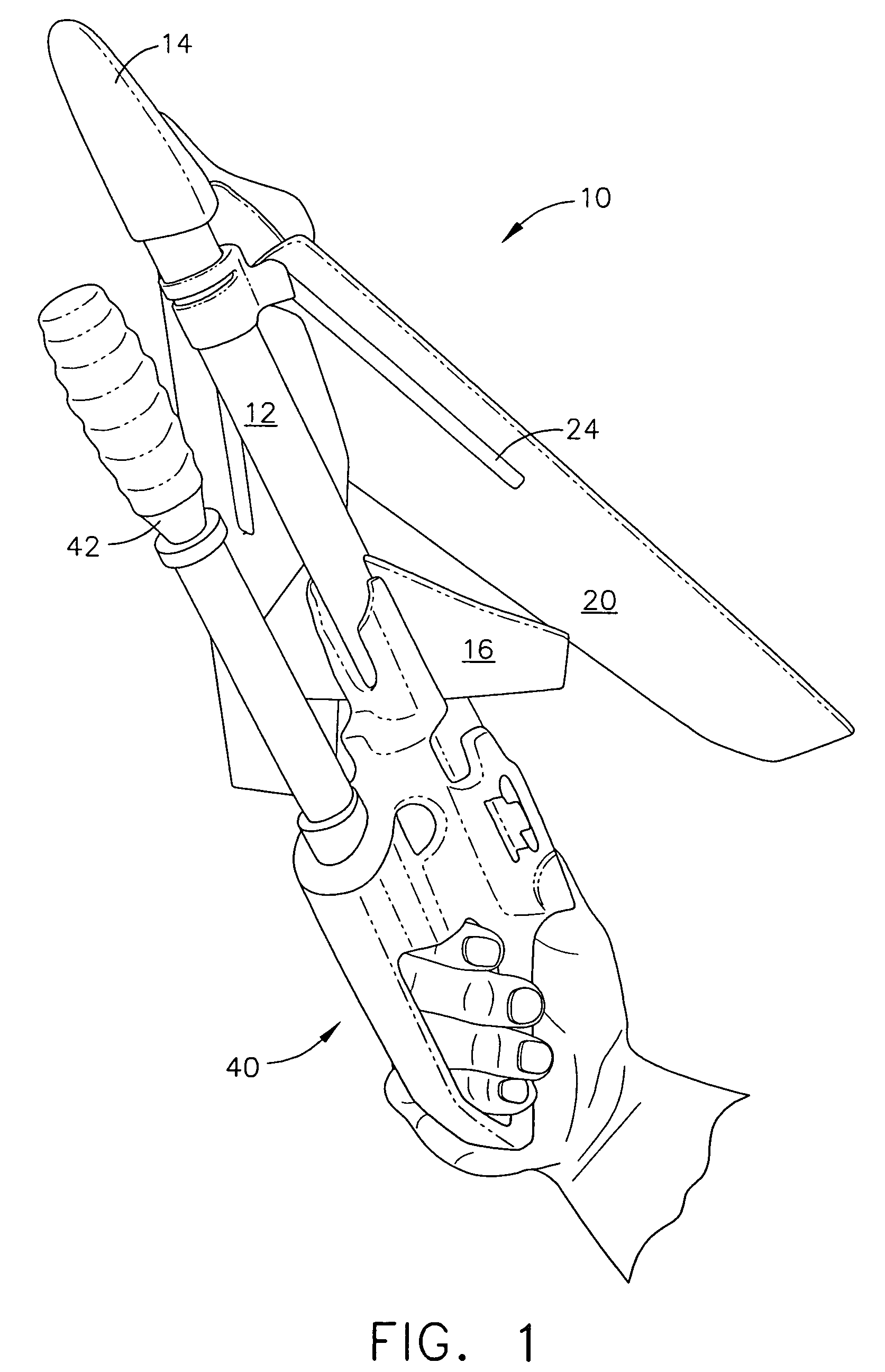
[0029]With reference to the drawings, FIG. 1 shows a handheld launcher 40 engaged with a glider 10. With reference to FIGS. 1 through 4, there is shown a glider 10 that has two pivoting, retractable wings 20 that deploy, or sweep outward and forward, sometime after launch. The glider 10 has a nose cone 14, a hollow fuselage 12, two wings 20 and four tail stabilizers 16. However, it will be appreciated that any suitable number of wings 20 or tail stabilizers 16 may be used. It will also be appreciated that the glider 10 need not have a cone-shaped nose. In addition, it will be appreciated that all or part of the fuselage 12 may be hollow. Still other configurations may be used.

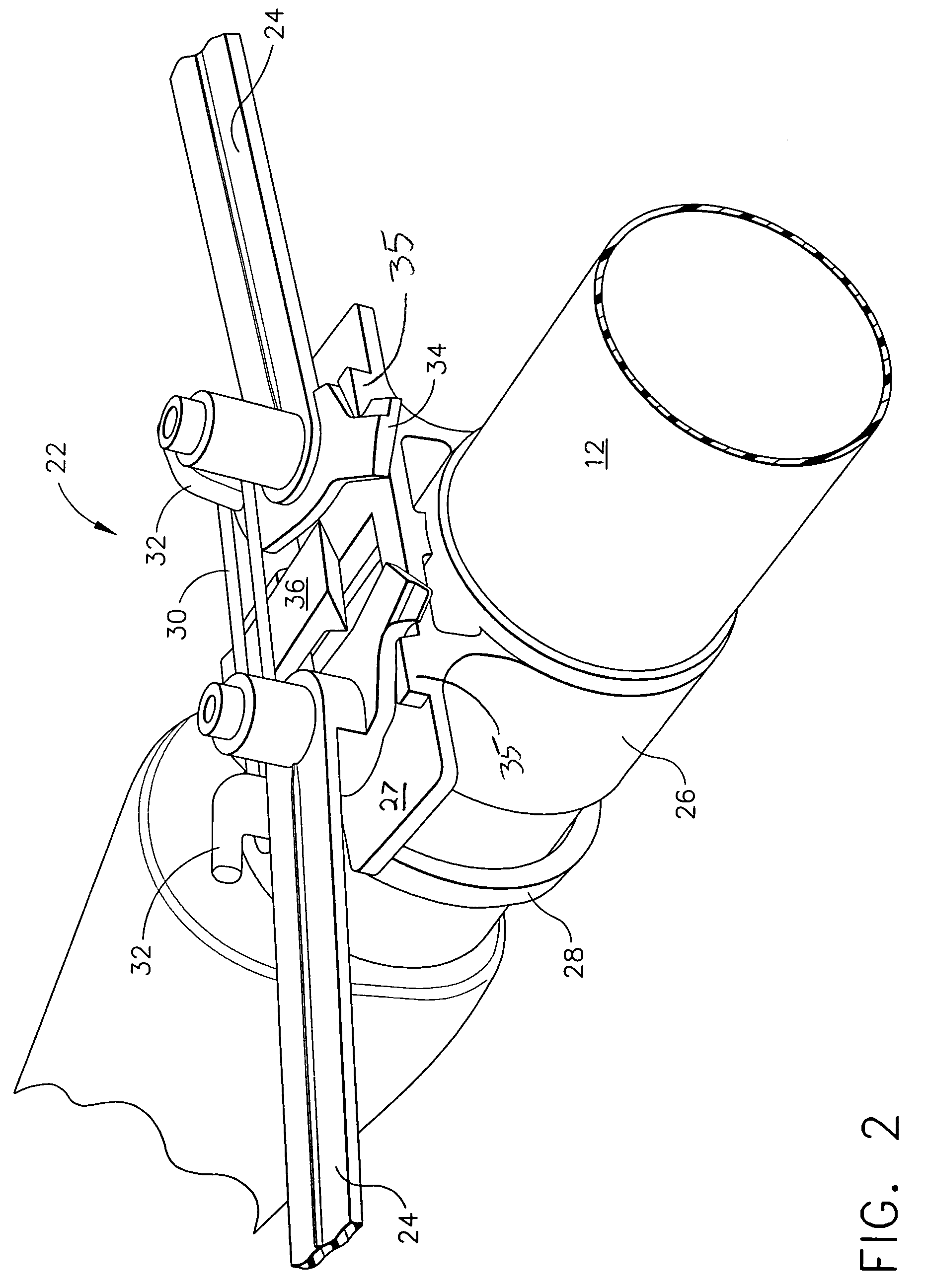
[0030]The glider 10 in the present example has a wing sweep mechanism 22 that is configured to hold the wings 20 in a retracted position, partially above the fuselage 12, as shown in FIG. 3. However, it will also be appreciated that a wing sweep mechanism 22 may simply hold the wings 20 near, but not necessaril...


PUM


Abstract

A glider toy has pivoting wings that may be locked in a retracted position prior to launch. Upon launching of the glider, the wings may be unlocked. During flight, the wings extend forward for an entertaining glide at the urging of one or more elastic members. A launcher includes an orientation-sensitive safety feature that limits the angles at which projectiles may be launched therefrom. The safety feature permits projectiles to be launched from the launcher only within approximately a generally upward, non-vertical angular range.

Description

[0001]This application claims priority benefit of the disclosure of U.S. provisional patent application 60 / 446,890 for Pneumatically Launched Folding Wing Glider Toy, filed Feb. 12, 2003.BACKGROUND OF THE INVENTION[0002]The present invention generally relates to toys, and more particularly to pneumatically projected glider aircraft toys.[0003]Aerial toys such as airplane gliders have long been used for education and entertainment. Such gliders have conventionally been propelled into flight by way of a sling shot mechanism or by a user throwing the glider into flight. Such gliders have been limited in terms of altitude due to the traditional means used to launch the glider, as well as the drag forces acting against the wings of the glider during its ascent. For example, as to conventional gliders launched by a sling shot mechanism, the maximum altitude of the glider is limited in part by the strength of the rubber band or similar elastic member comprising the launching mechanism. As ...

Claims


Application Information

Patent Timeline
IPC IPC(8): B64F1/04A63H27/00A63H27/14A63H27/26A63H29/16
CPCA63H27/005A63H27/007A63H29/165A63H27/14A63H27/06
Inventor POESCH, ERIC S.O'CONNOR, MICHAEL J.SHROCK, JOEL A.RASMUSSEN, RUSSELL G.
Owner TBDUM LLC
Learn More