Passenger sitting/sleeping arrangement

a technology for passengers and seats, applied in the direction of aircraft accessories, propellers, fuselages, etc., can solve the problems of preventing the adoption of volume-intensive solutions and difficult to achieve this goal, and achieve the effect of maximizing the comfort of passengers

Inactive Publication Date: 2006-07-18
JACOB EMIL
View PDF26 Cites 16 Cited by
  • Summary
  • Abstract
  • Description
  • Claims
  • Application Information

AI Technical Summary

Benefits of technology

[0004]The principle object of the invention is to provide a passenger accommodation arrangement which maximizes the comfort of passengers by providing the choice of both sitting and fully reposed sleeping positions in the same passenger accommodation unit.
[0007]Space utilization efficiency is further increased by the use of compartments which include a stair and vertically stacked, individual passenger units located on both sides of the stair. The stair is used by passengers to access the individual, stacked units and has landings which function to aid the passenger in accessing the units. Multiple compartments are arranged along the longitudinal dimension of the aircraft as well as on both sides of the aisle of the aircraft. The number of units stacked one above the other is a function of the specific dimensions of the air into which the arrangement is installed. While space utilization efficiency is maximized by stacking as many units as possible on one another, passenger comfort is optimized by limiting the number of units so stacked. The optimum arrangement must take into account the available space in the aircraft.

Problems solved by technology

Attainment of this goal has been difficult given the concurrent need to optimize the efficient use of space in aircraft.
The inefficient seating / bedding arrangements of the prior art coupled with the pressure to maximize per-flight revenues have precluded adoption of volume-intensive solutions which would otherwise be available to allow achievement of these goals.

Method used


Image

  • Passenger sitting/sleeping arrangement
  • Passenger sitting/sleeping arrangement
  • Passenger sitting/sleeping arrangement

Examples


Embodiment Construction

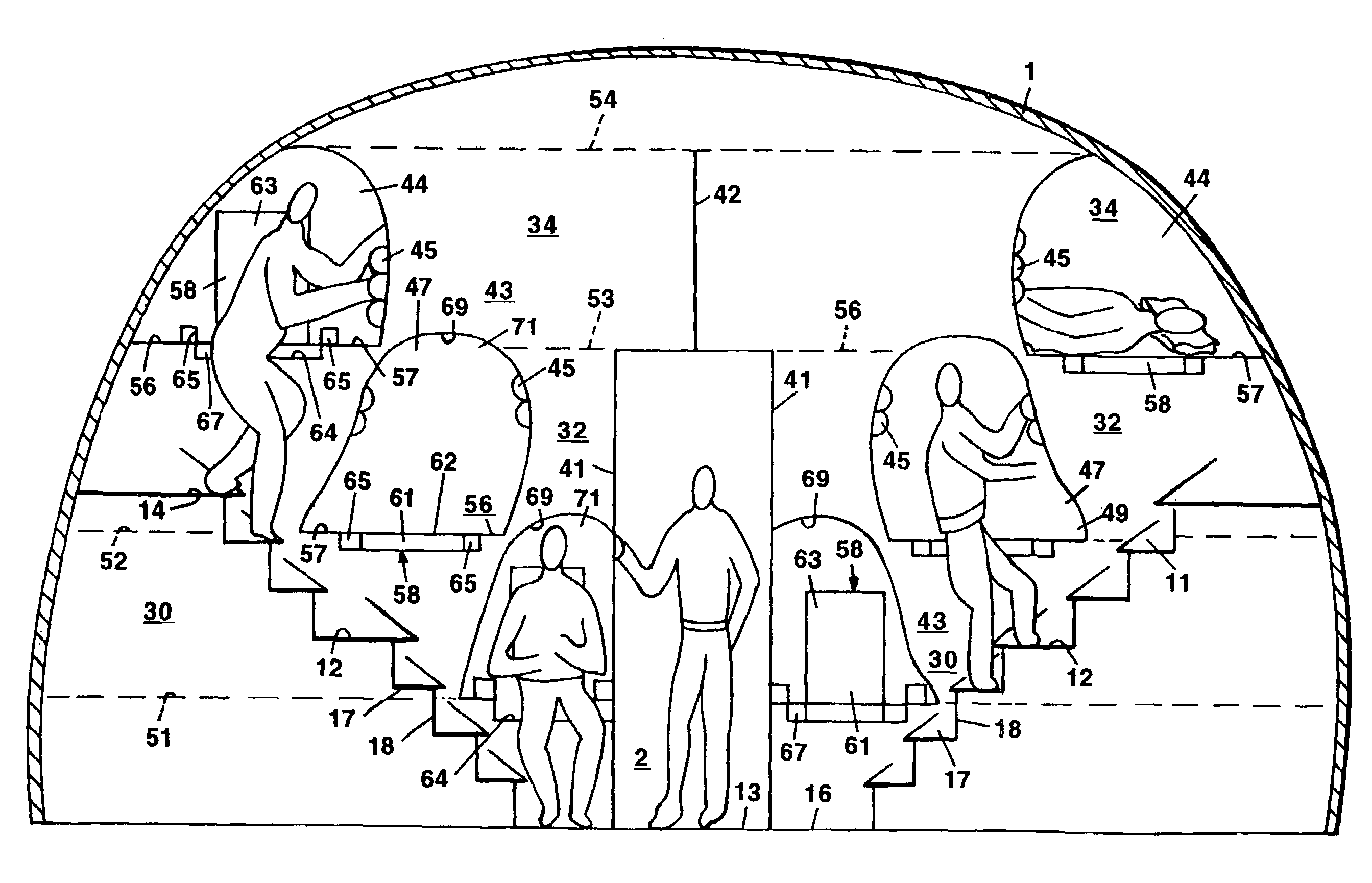
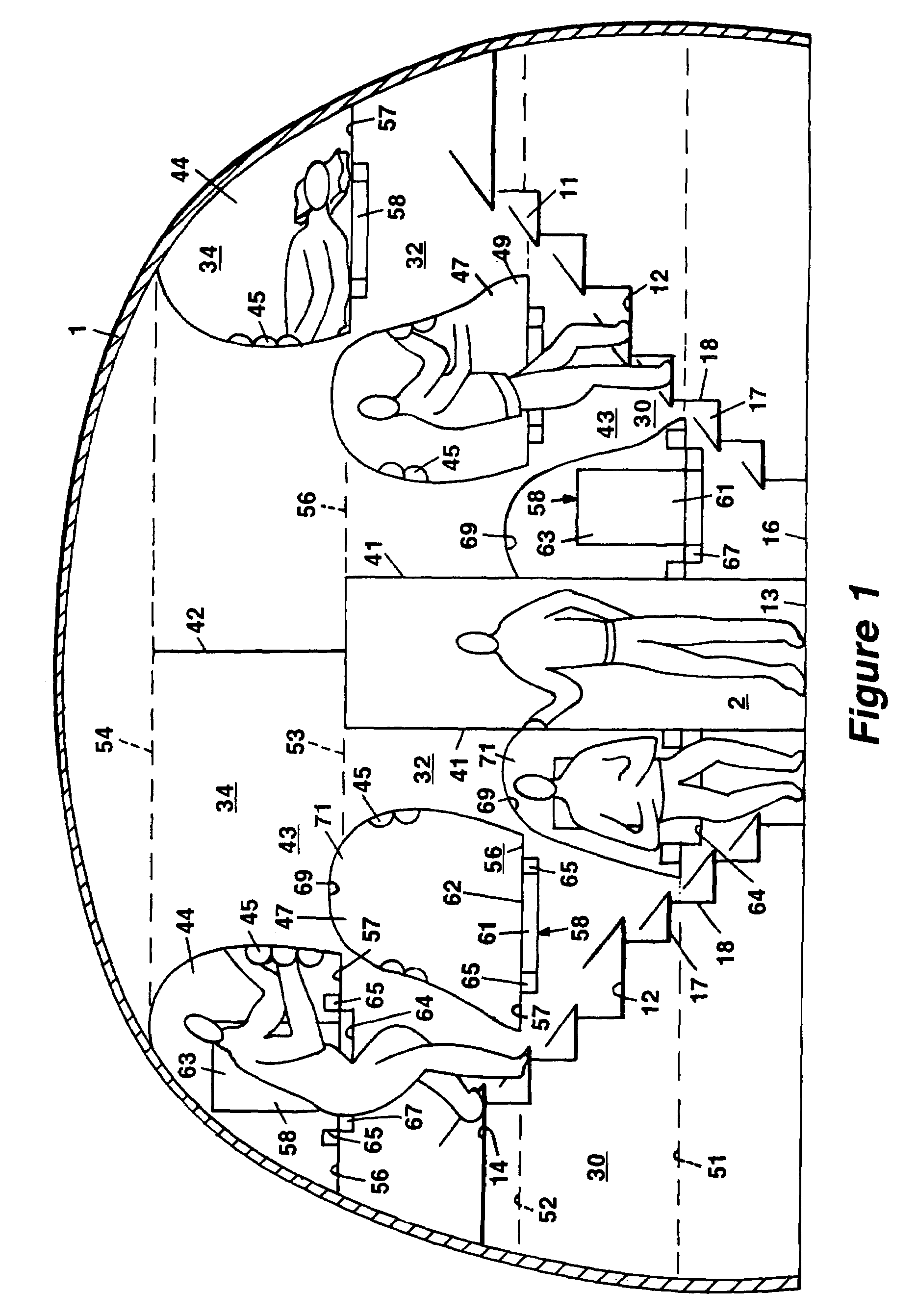
[0013]The passenger sitting / sleeping arrangement of the invention, as incorporated into a passenger transport aircraft, will now be specifically described with reference to FIGS. 1–3, wherein the same reference numbers will be used to identify similar functional components in the various structures. Referring to FIG. 1, the aircraft is seen to include a fuselage 1 and a longitudinally extending main aisle 13.

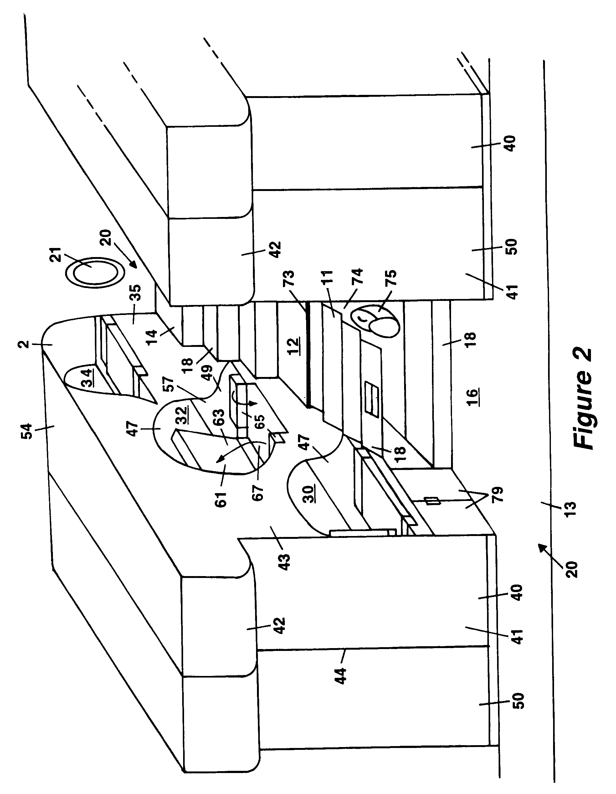
[0014]The passenger sitting / sleeping arrangement of the invention comprises a passenger compartment 20, as best seen in FIGS. 2 and 3. The compartment is made up of modules 40 and 50 together with a stair 11 located between the modules 40 and 50. It should be understood that the compartment 20 would usually be one of several similar passenger compartments arranged along at least part of, or perhaps the entire length of, the aircraft. Both the modules 40 and 50 and the stair 11 are arranged to have their longitudinal dimension extend in a direction generally transverse to and awa...


PUM


Abstract

In accordance with the present invention, there is provided a passenger accommodation arrangement for aircraft which provides both a highly efficient use of available aircraft space and a high level of comfort for passengers. In particular, the novel arrangement allows passengers to easily and comfortably switch between sitting and sleeping positions. The arrangement provides for multiple compartments arranged transversely with respect to the longitudinal dimension of the aircraft. Each compartment includes a stair and multiple, individual passenger accommodation units arranged one above another on each side of the stair. Each unit contains structure which allows a passenger to switch between a sitting position, in which the passenger is supported on a seat surface, and a fully reposed position in which the passenger is supported on a substantially flat, horizontal sleeping surface. Conversion between sitting and sleeping positions is enabled by moveable sections which form part of the passenger bed in a first position and part of the passenger seat in a second position. Passenger units which are vertically adjacent to one another may include complementary and vertically aligned formations to optimize the usable height of the units.

Description

CROSS-REFERENCE TO RELATED PATENT APPLICATIONS[0001]This application claims the benefit of Provisional Patent Application Ser. No. 60 / 584,329, filed on Jul. 1, 2004, the disclosure of which is incorporated in its entirety hereinto by reference.BACKGROUND OF THE INVENTION[0002]The invention relates to passenger accommodation arrangements for use in transportation vehicles such as aircraft, trains, busses and the like. More particularly, the present invention relates to passenger accommodation arrangements which easily permit a passenger to convert from a sitting position to a fully reposed sleeping position.[0003]It has long been a goal of the passenger transportation industry cost effectively to provide comfortable seating and bedding arrangements for passengers. Given the ever increasing volume of long, non-stop flights over 6 hours in duration, it has become even more desirable to provide a truly restful passenger accommodation. Attainment of this goal has been difficult given the...

Claims


Application Information

Patent Timeline
Patent Type & Authority Patents(United States)
IPC IPC(8): B64C11/00
CPCB64D11/00B64D11/0604B64D11/0601
Inventor JACOB, EMIL
Owner JACOB EMIL
Why Eureka
Try Eureka