Finger unit for robot hand

a robot hand and finger unit technology, applied in the field of finger units, can solve the problems of insufficient instantaneous maximum output torque of servomotors, insufficient encoders with a sufficiently narrow diameter, and high resolution

Active Publication Date: 2006-07-18
HARMONIC DRIVE SYST IND CO LTD
View PDF8 Cites 87 Cited by
  • Summary
  • Abstract
  • Description
  • Claims
  • Application Information

AI Technical Summary

Benefits of technology

[0021]To allow a bevel gear to move without backlash, a spring plate should be mounted on an external end surface of the bearings in order to restrict the axial bias of the driven-side bevel gear fixed to the joint shaft.

Problems solved by technology

However, such actuators are not yet commercially available, and there are as yet no related products that could serve as components satisfying such specifications.
In other words, the instantaneous maximum output torque of servomotors is insufficient, reduction gears have a large backlash of 1° angle at the output shaft even in the case of multistage planetary types, and there are no encoders that have a sufficiently narrow diameter, low weight, and high resolution.
With each these options, however, the joint portion acquires excessive dimensions and mass, switching during operation is too slow, and other drawbacks are encountered.
The use of a regular bevel gear is problematic from the viewpoint of backlash and smooth rotation.
Conventional fingers mostly have joints that deflect to the inside of the hand in-conjunction with other fingers, and to a large extent it is impossible to perform cooperative work between fingers or to perform various other movements by using such fingers in the palm of a robot hand.

Method used


Image

  • Finger unit for robot hand
  • Finger unit for robot hand
  • Finger unit for robot hand

Examples


Embodiment Construction

[0038]An articulated finger unit for a high-speed robot hand to which the present invention has been applied is described below with reference to the drawings.

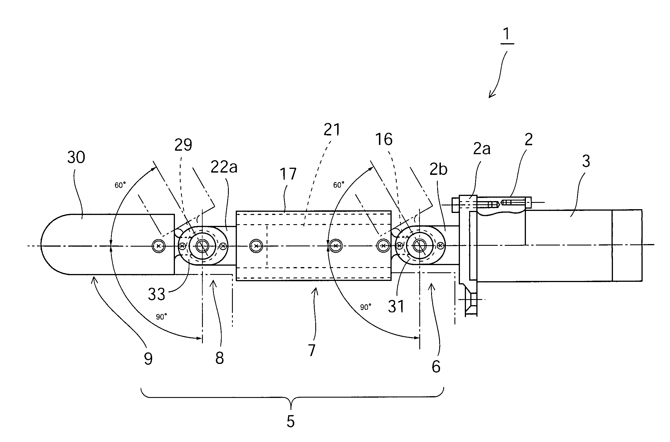
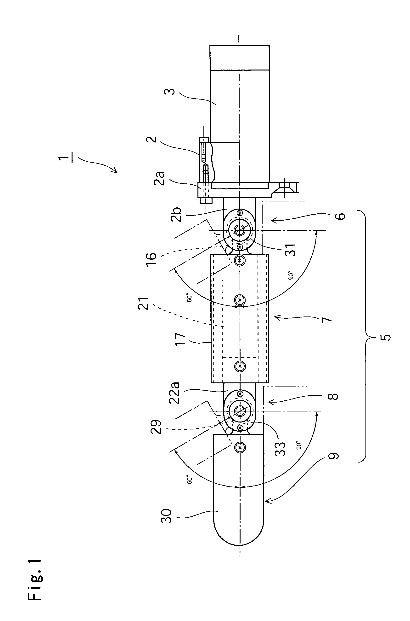
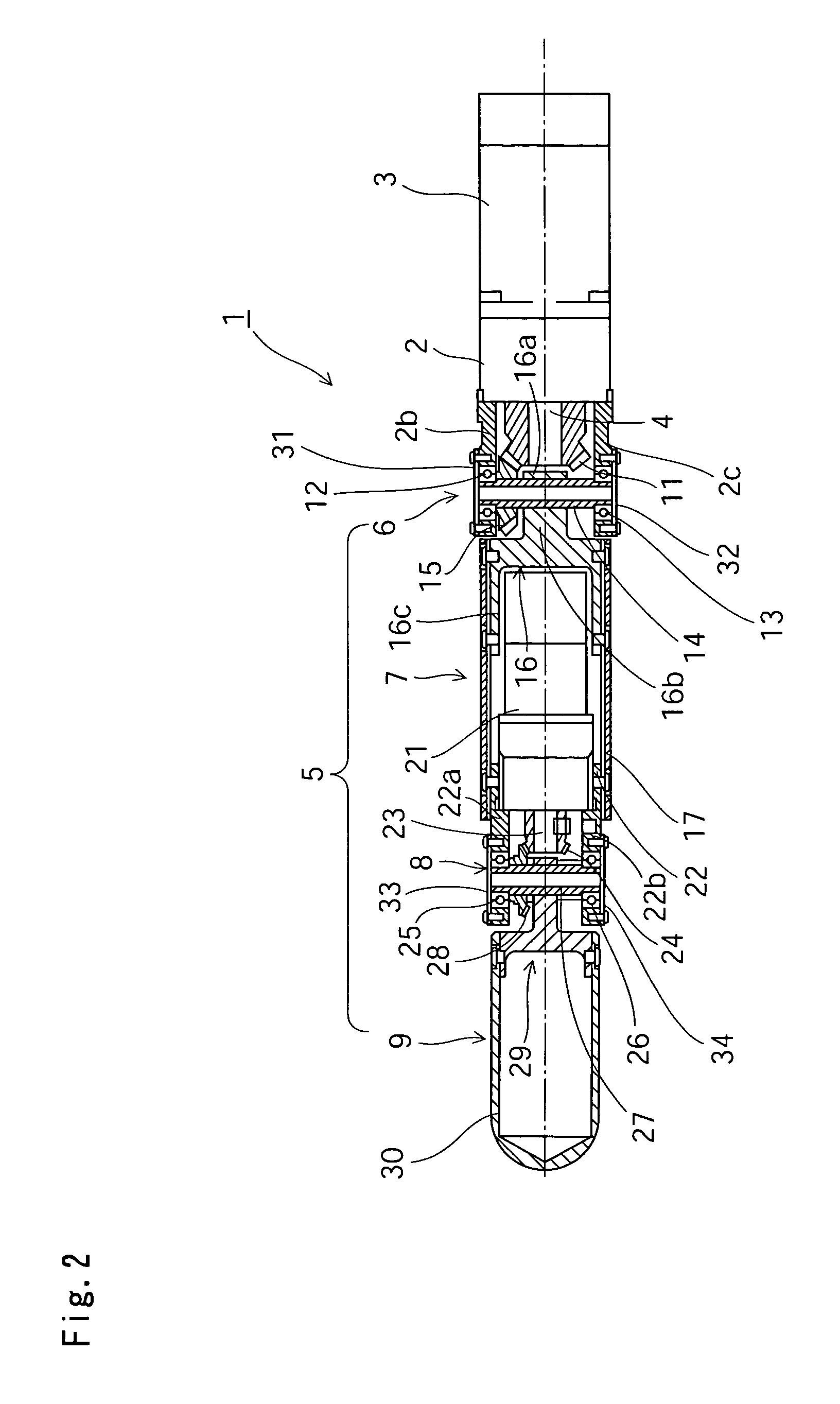
[0039]FIG. 1 is a top view that shows an articulated finger unit for a high-speed robot hand related to the present embodiment, and FIG. 2 is a cross-sectional view thereof. FIGS. 3A and 3B are respectively a cross-sectional view showing a joint portion on a finger base side of the articulated finger unit, and a top view showing a connecting member on the finger base side incorporated therein. FIGS. 4A and 4B are respectively a cross-sectional view showing a joint portion on a fingertip side of the articulated finger unit, and a top view showing a connecting member on the fingertip side incorporated therein.

[0040]With reference to the drawings, an articulated finger unit 1 has a mounting flange 2, an actuator 3 mounted on the mounting flange 2, and a finger main body unit 5 connected to a rotational output shaft 4 of the actua...


PUM


Abstract

An articulated finger unit has a two-jointed structure comprising a joint portion on a finger base side, a finger base portion, a joint portion on a fingertip side, and a fingertip portion; the joint portion on the finger base side has a drive-side bevel gear fixed to a rotational output shaft of an actuator, a driven-side bevel gear coaxially fixed to a joint portion that is perpendicular to the rotational output shaft, and a connecting member wherein an annular boss is fixed to the driven-side bevel gear and wherein a tip portion extends in a fork shape; and a cover on the finger base side is connected to the connecting member. A rotation of the rotational output shaft is converted to rotational movement of the joint shaft by way of a pair of bevel gears, and the connecting member fixed to the joint shaft turns right and left at an angle of 90° or more about the joint shaft. The finger unit suitable for use in a robot hand that moves at high speed and with precision can be realized.

Description

CROSS-REFERENCE TO RELATED APPLICATIONS[0001]This application claims priority under 35 U.S.C. § 119 to JP 2002-293651 filed in Japan on Oct. 7, 2002, the entire content of which is hereby incorporated by reference.BACKGROUND OF THE INVENTION[0002]1. Field of the Invention[0003]The present invention relates to a finger unit suitable for use in a robot hand that is capable of accurately catching flying objects and the like at high speeds.[0004]2. Description of the Related Art[0005]Finger units for robot hands commonly have an articulated structure, and a high torque actuator that is small, lightweight, and as precise as possible is required for driving each finger joint in order to quickly and reliably perform gripping, picking, and throwing actions with the articulated finger unit.[0006]Such an actuator must include a motor that fits inside the dimensions of the finger, operates at high speed, and can generate high instantaneous maximum output torque; a reduction gear that has minim...

Claims


Application Information

Patent Timeline
Patent Type & Authority Patents(United States)
IPC IPC(8): B25J15/10B25J15/08B25J9/10B25J15/00
CPCB25J15/0009B25J9/102
Inventor KAMEDA, HIROSHIKOBAYASHI, KIYOTOKOYAMA, JUNJIMORIMOTO, TEIZOSASAHARA, MASAKATSU
Owner HARMONIC DRIVE SYST IND CO LTD
Why Eureka
Try Eureka