Eureka AIR delivers breakthrough ideas for toughest innovation challenges, trusted by R&D personnel around the world.

Ophthalmic fluid dispenser

a technology of ophthalmic fluid and dispenser, which is applied in the direction of liquid transfer devices, eye treatment, single-unit apparatuses, etc., can solve the problems of cost in the case of expensive medications, design gives little control over the administration of ophthalmic products, and the cost of known devices suffers from various limitations

Inactive Publication Date: 2006-07-18
SKOLIK STEPHANIE
View PDF23 Cites 4 Cited by
  • Summary
  • Abstract
  • Description
  • Claims
  • Application Information

AI Technical Summary

Benefits of technology

"The invention is a dispenser for ophthalmic products that allows patients to self-treat without needing exceptional mechanical dexterity. It is designed to dispense a predetermined dose of ophthalmic product in the form of a narrow spray. It can be connected to a bottle of ophthalmic solution and avoids contacting the eye, thereby eliminating the possibility of contamination. The device is made of plastic, has a low cost, and is designed to reliably dispense a limited quantity of ophthalmic solution each time it is operated. The amount of fluid that is dispensed is metered by a member that has a cavity which is movable from a first position in which it receives fluid to a second position in which it allows the fluid to pass to a holding chamber, and the device further includes means for removing fluid from the holding chamber in the form of a spray, with the spray delivery being accomplished by an air stream injected into the holding chamber."

Problems solved by technology

In the application of certain medical preparations, it is necessary that the fluid be delivered in a fairly well-defined volume since an excessive dosage may result in improper physiological effects.
A contributing factor in requiring the delivery of a specified dose is the matter of cost in the case of expensive medications.
Accordingly in the case of self-treatment, a further consideration is the need to achieve delivery to the targeted eye without the patient having to assume a strained body, head or hand position, since such a strained posture may result in forced errors.
Such known devices suffer from various limitations.
Drop applicators rely on impact by gravity, but common designs give little control over the administration of ophthalmic products.
Certain devices are difficult to operate except with proper orientation of the device.
While prior spray applicators tend to be independent of applicator orientation and give a distributed spray, they are limited in controlling the amount that is dispensed.
In some devices contamination can result from contaminants being drawn into the applicator after some product has been dispensed.

Method used


Image

  • Ophthalmic fluid dispenser
  • Ophthalmic fluid dispenser
  • Ophthalmic fluid dispenser

Examples


Embodiment Construction

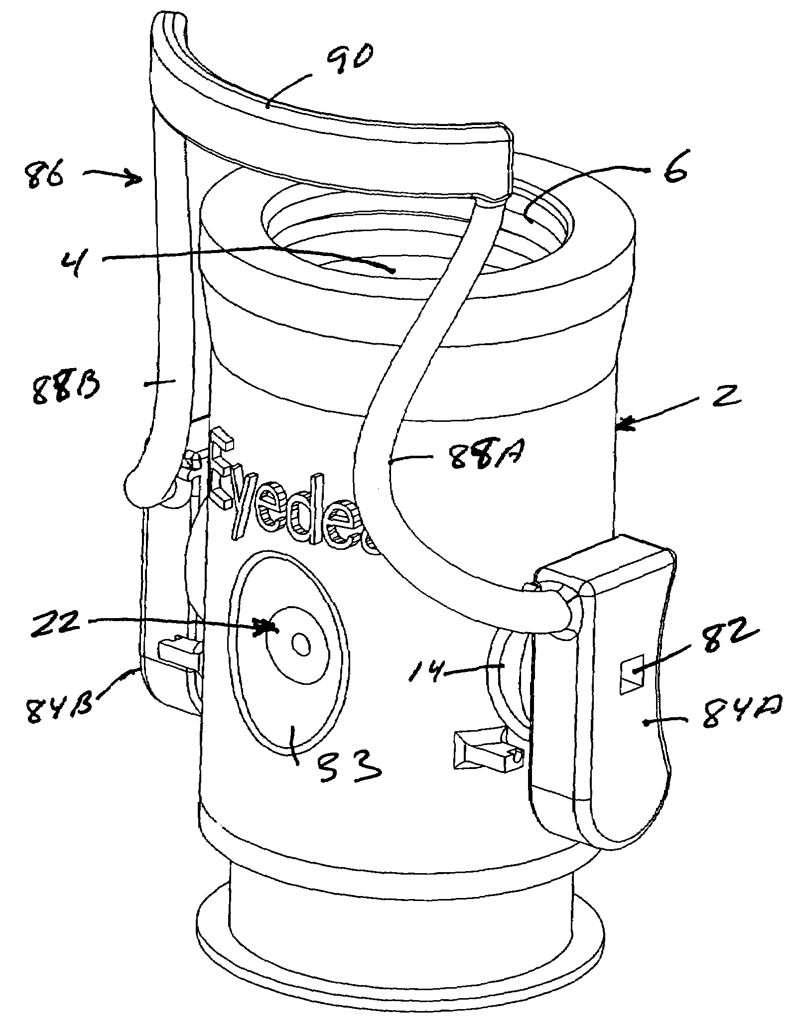
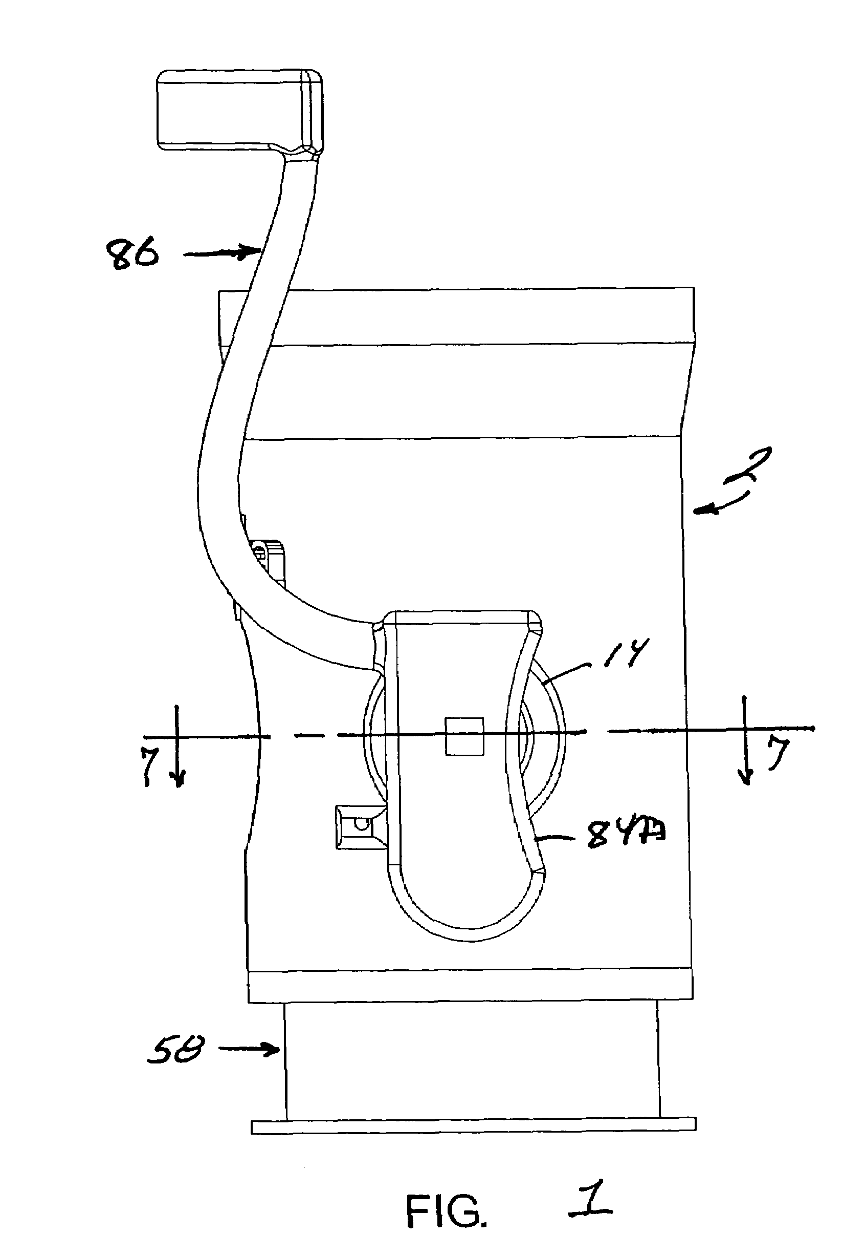
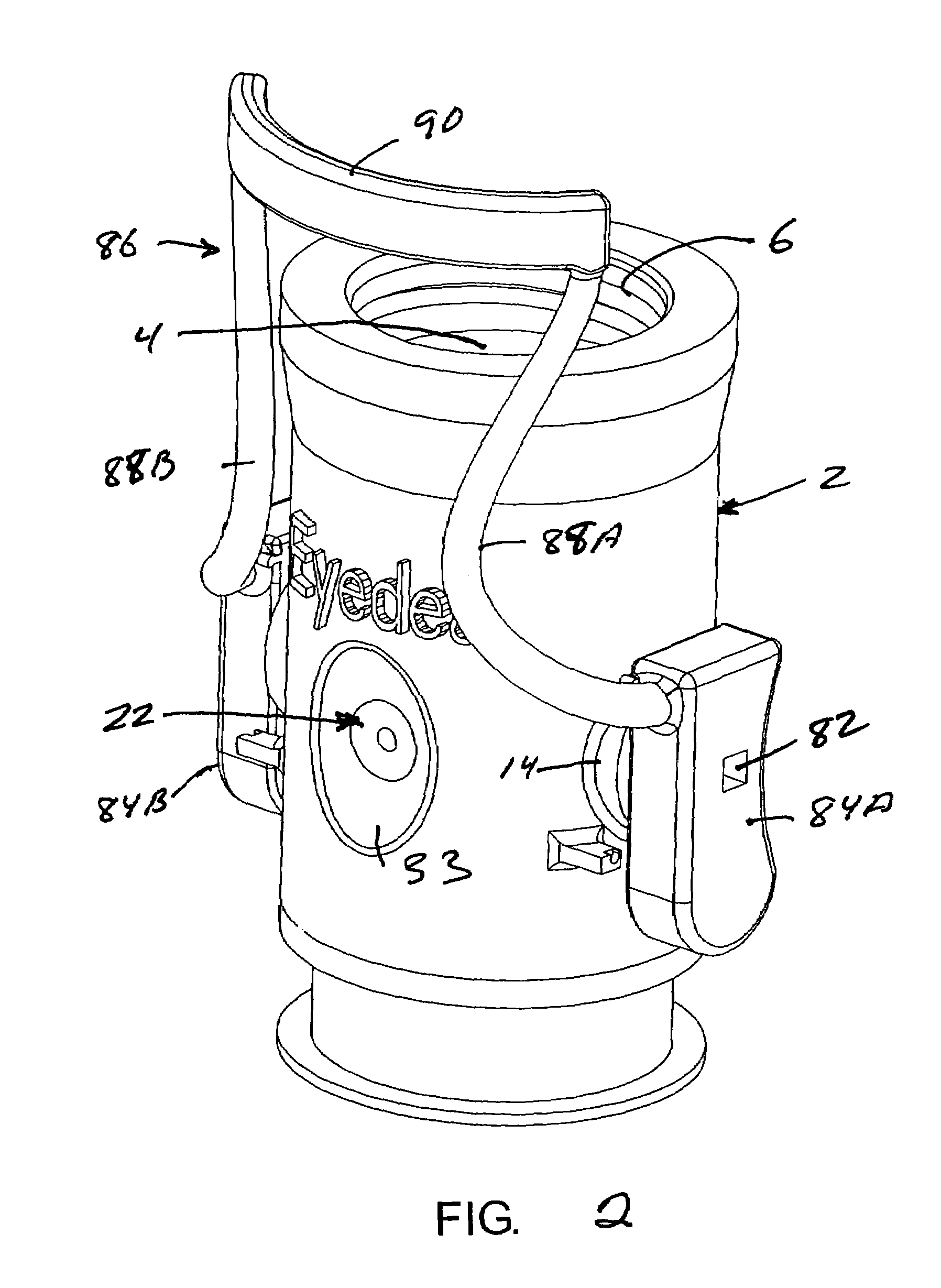
[0023]Referring to FIGS. 1–7, a dispenser device constituting a preferred embodiment of the present invention comprises a housing in the form of a body 2 having an axial cavity 4 with an enlarged outer end characterized by a screw thread 6 for use in attaching a bottle 8 (FIG. 12) containing an ophthalmic liquid (not shown). The inner end of cavity 4 is intersected by a diametrically-extending bore 12, resulting in the formation of a hole 13 (FIGS. 1 and 2) at the bottom cavity 4. The diameter of hole 13 is equal to or slightly greater than that of metering cavity 18 described hereinafter. Preferably, but not necessarily, the outer surface of body 2 is provided with an outwardly projecting circular boss 14 at each end of bore 12. The outer face of each boss is flat and acts as a bearing surface for the operating lever 86 described below.

[0024]Mounted within bore 12 is a metering member 16 in the form of a cylindrical shaft having a cavity 18 located intermediate its ends. Cavity 18 ...


PUM


Abstract

An eye fluid applicator is adapted for connection to the mouth of a bottle containing an ophthalmic liquid and comprises means for dispensing ophthalmic liquid from the bottle in metered amounts and in a manner which avoids contacting the eye with the applicator. The applicator includes a metering member that has a metering cavity for holding a small amount of liquid and which is movable between a first position in which the metering cavity is disposed to receive liquid from the container and a second position in which it allows the liquid to spill out of the cavity into a holding chamber, and manually operable pneumatic means for removing liquid from the holding chamber and expelling it through a discharge orifice in the form of a narrow spray.

Description

FIELD OF THE INVENTION[0001]The invention pertains to delivery of ophthalmic fluids to the eye and more particularly to a device for dispensing ophthalmic fluid in small controlled doses.BACKGROUND OF THE INVENTION[0002]Ophthalmic products are available for treatment of various conditions. For example, the treatment of glaucoma requires frequent daily administrations of certain ophthalmic compositions having the desired pressure-relieving action. Ophthalmic fluids also are used to relieve eye strain and irritation caused by smog, allergens such as pollen and dust, smoking, and swimming, etc. In the application of certain medical preparations, it is necessary that the fluid be delivered in a fairly well-defined volume since an excessive dosage may result in improper physiological effects. Another requirement is that the need to properly target the dose of ophthalmic medication. A contributing factor in requiring the delivery of a specified dose is the matter of cost in the case of ex...

Claims


Application Information

Patent Timeline
Patent Type & Authority Patents(United States)
IPC IPC(8): A61M35/00A61M11/00A61F9/00A61M11/02B05B11/06
CPCA61F9/0008A61M11/02B05B11/061A61F9/0026A61M2205/075
Inventor SKOLIK, STEPHANIE
Owner SKOLIK STEPHANIE
Why Eureka
Eureka Blog
Learn More