Electric current measuring device, current sensor, electric trip unit and breaking device comprising such a measuring device

a technology of current sensor and measuring device, which is applied in the direction of magnetic measurement, base element modification, instruments, etc., can solve the problems of being too sensitive to external phenomena of polygons, difficult to industrialize solutions using closed toroids, and complex winding of toroids. achieve the effect of reducing volume, less sensitive, and simplifying industrialization

Active Publication Date: 2006-07-18
SCHNEIDER ELECTRIC IND SAS
View PDF8 Cites 30 Cited by
  • Summary
  • Abstract
  • Description
  • Claims
  • Application Information

AI Technical Summary

Benefits of technology

[0014]The object of the invention is therefore to remedy the drawbacks of the state of the art so as to propose an electric current measuring device that is less sensitive to external disturbances, is of reduced volume, and simplified industrialization.

Problems solved by technology

Although they are very efficient, solutions using a closed toroid remain difficult to industrialize due to the geometry of the toroid.
Winding of a toroid in fact remains complex and this is particularly true when the size of the current measuring device is small.
However, these solutions sometimes present the drawback of being too sensitive to phenomena external to the polygon.
This solution does not fully solve the problem relating to the influence of external fluxes on current measurement.
In addition, problems of fitting the coils on their support are encountered.
Although they reduce the influence of stray external fluxes, these cores do however end up saturating in the presence of strong currents.
In addition, the presence of these cores makes connection of the coils to one another more complex.

Method used


Image

  • Electric current measuring device, current sensor, electric trip unit and breaking device comprising such a measuring device
  • Electric current measuring device, current sensor, electric trip unit and breaking device comprising such a measuring device
  • Electric current measuring device, current sensor, electric trip unit and breaking device comprising such a measuring device

Examples


Embodiment Construction

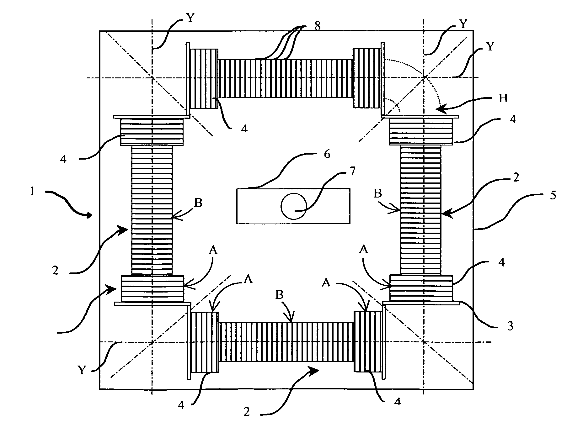
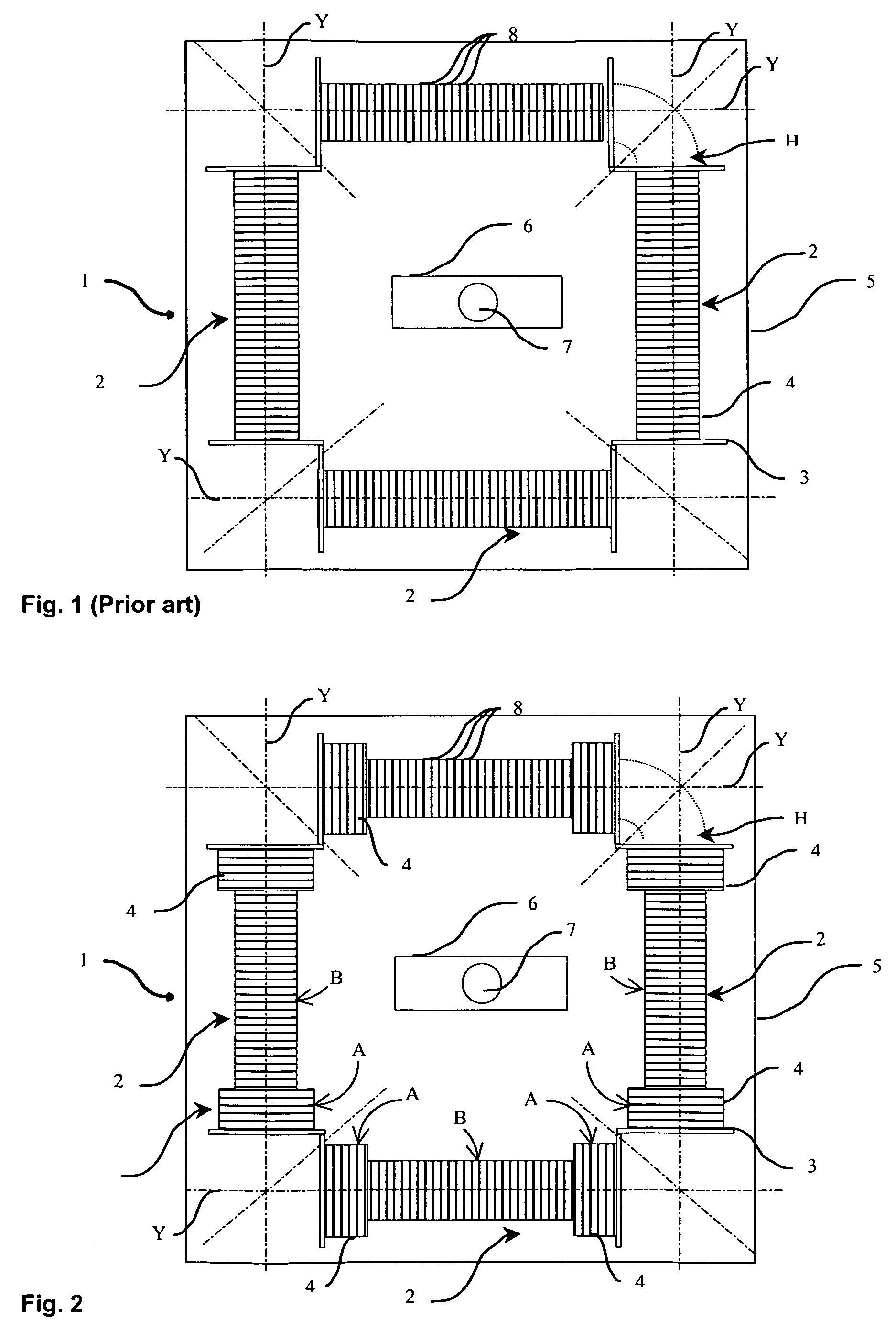
[0037]The current measuring device 1 comprises at least three linear coils 2 electrically connected in series and forming a closed polygonal outline. According to the preferred embodiment of the invention represented in FIG. 2, the current measuring device 1 comprises four linear coils 2 arranged in the same plane. The longitudinal axis Y of each coil is perpendicular to the respective longitudinal axes of the two coils placed physically next to it.

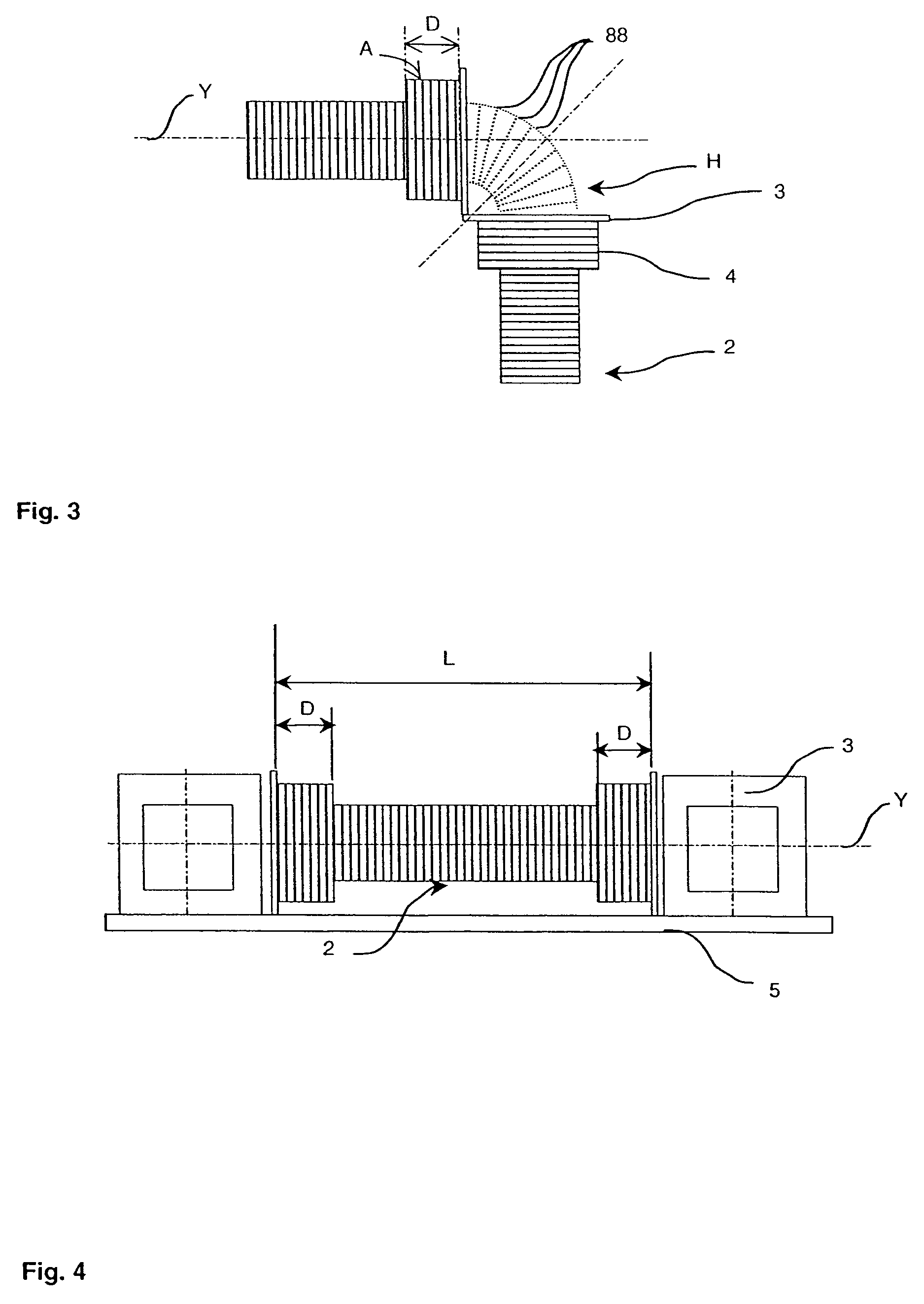
[0038]Each coil is composed of a hollow, rigid or semi-rigid, shell of linear shape, made of non-magnetic material, and having a cylindrical, square, rectangular or ovoid cross-section. A metallic wire made of copper or a copper-based alloy is wound on the shell.

[0039]Generally, the shells of known sensors have cross-sections of circular shape. However, such a shape does not enable a maximum cross-section to be had when the space or volume set aside for the sensors is limited. In the embodiment, the cross-section of the shells of the coil...


PUM


Abstract

The Rogowski type current measuring device comprises at least three coils electrically connected in series and forming a closed polygonal outline designed to surround a conductor to perform current measurement. The local inductance of at least one of the ends of said coils is greater than the local inductance towards the central part of said coils.

Description

[0001]The present application is based on French Application No. 04 05199, filed May 13, 2004, which application is incorporated herein by reference in its entirety.BACKGROUND OF THE INVENTION[0002]The invention relates to a current measuring device of the Rogowski type comprising at least three coils electrically connected in series and forming a closed polygonal outline designed to surround a conductor to perform current measurement.STATE OF THE ART[0003]The use of current measuring devices comprising Rogowski type inductive sensors is extensively described in the literature.[0004]Rogowski type current measuring devices comprise a support made of non-magnetic material placed around a current conductor or line wherein the current to be measured flows. A conducting wire is coiled onto the support to form a secondary winding. The assembly forms a transformer where said current conductor or line constitutes a primary winding and said secondary winding supplies a measurement signal. Th...

Claims


Application Information

Patent Timeline
Patent Type & Authority Patents(United States)
IPC IPC(8): G01R15/18G01R15/20
CPCG01R15/181G01R19/00
Inventor BUDILLON, GILLESBUFFAT, SEBASTIENHOUBRE, PASCALTOTI-BUTTIN, FREDERIC
Owner SCHNEIDER ELECTRIC IND SAS
Why Eureka
Try Eureka