Supercharge Your Innovation With Domain-Expert AI Agents!

Constant power and temperature coil

a constant power and temperature coil technology, applied in the field of magnetic field generation, can solve the problems of reducing the rate at which the coils reach a stable temperature, affecting the quality of the pattern being written by the electron beam on the substrate, and affecting the quality of the pattern

Inactive Publication Date: 2006-07-18
MARTIN GLENN HENRY +2
View PDF10 Cites 5 Cited by
  • Summary
  • Abstract
  • Description
  • Claims
  • Application Information

AI Technical Summary

Benefits of technology

[0018]Accordingly, it is the general object of the present invention to provide a novel and useful magnetic coil for generating magnetic fields in which the problems described above are eliminated.
[0019]A more specific object of the present invention is to provide a novel and useful deflection coil for generating magnetic fields in which the problems described above are eliminated.
[0020]Another more specific object of the present invention is to provide a novel and useful lens coil for generating magnetic fields which form lenses for particle beams which pass through them, in which the problems described above are eliminated.

Problems solved by technology

The problem is first, with the differences between the initial and final temperatures as a new spot size, intensity or scan deflection is selected.
The second part of the problem is the rate at which the coils reach a stable temperature after these changes have been made.
However, when trying to hold accuracy of beam position to within a few nanometers, a change in the position of the beam, the scan length or the beam deflection, of hundreds or even tens of nanometers can be very serious and result in the degradation of the quality of a pattern being written by the electron beam on a substrate.
The degradation of pattern quality can be so severe, when temperature driven beam drift results in only a few tens of nanometers of beam position change, that a pattern on a very expensive mask becomes useless.
Likewise temperature drift can cause changes in spot current, spot size and spot shape which can render a pattern on a very expensive mask useless.
Vector particle beam machines are particularly sensitive to this problem.
This constant variation of average power applied to the deflection coils makes it very difficult to control the internal temperature of the coils and column.
So there is little opportunity for dissipating the power which is being applied to the coils.
Any path for energy to leave the coils is very slow.
However, this method has significant drawbacks.
As a result the heat transfer between the coils and the heat exchange elements is still slow.
Consequently, hot and cold spots build up within the coil.
As a result, temperature drift still occurs.
This is time consuming and often inaccurate.
While it is possible to wait for the temperature to stabilize, this results in a significant cost in throughput.
The problem with this method is the same as with fluid cooling.
This results in hot and cold spots.
This is also time consuming and approximate at best.
Generally, though, temperature control of lens and centering coils is concentrated mainly in controlling the temperature of the driving electronics and amplifiers while the temperatures of the actual lenses and centering coils are not addressed.
Moreover, lenses and centering coils are not adjusted as often as deflection fields.
Even more generally the same problems are encountered in electrical servo motors for positioning a stage holding a substrate under the particle beam.
Even more generally, the same problems may be encountered in many electrical coils producing magnetic fields where temperature control is critical.
Even more generally, the same problems may be encountered in a device where a current element is placed in an externally induced magnetic field to produce a force or other linear effect.

Method used


Image

  • Constant power and temperature coil
  • Constant power and temperature coil
  • Constant power and temperature coil

Examples


Embodiment Construction

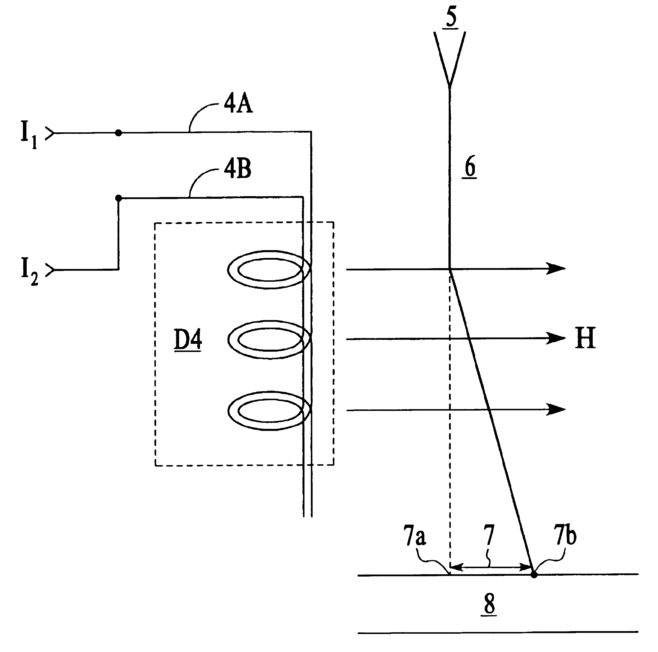
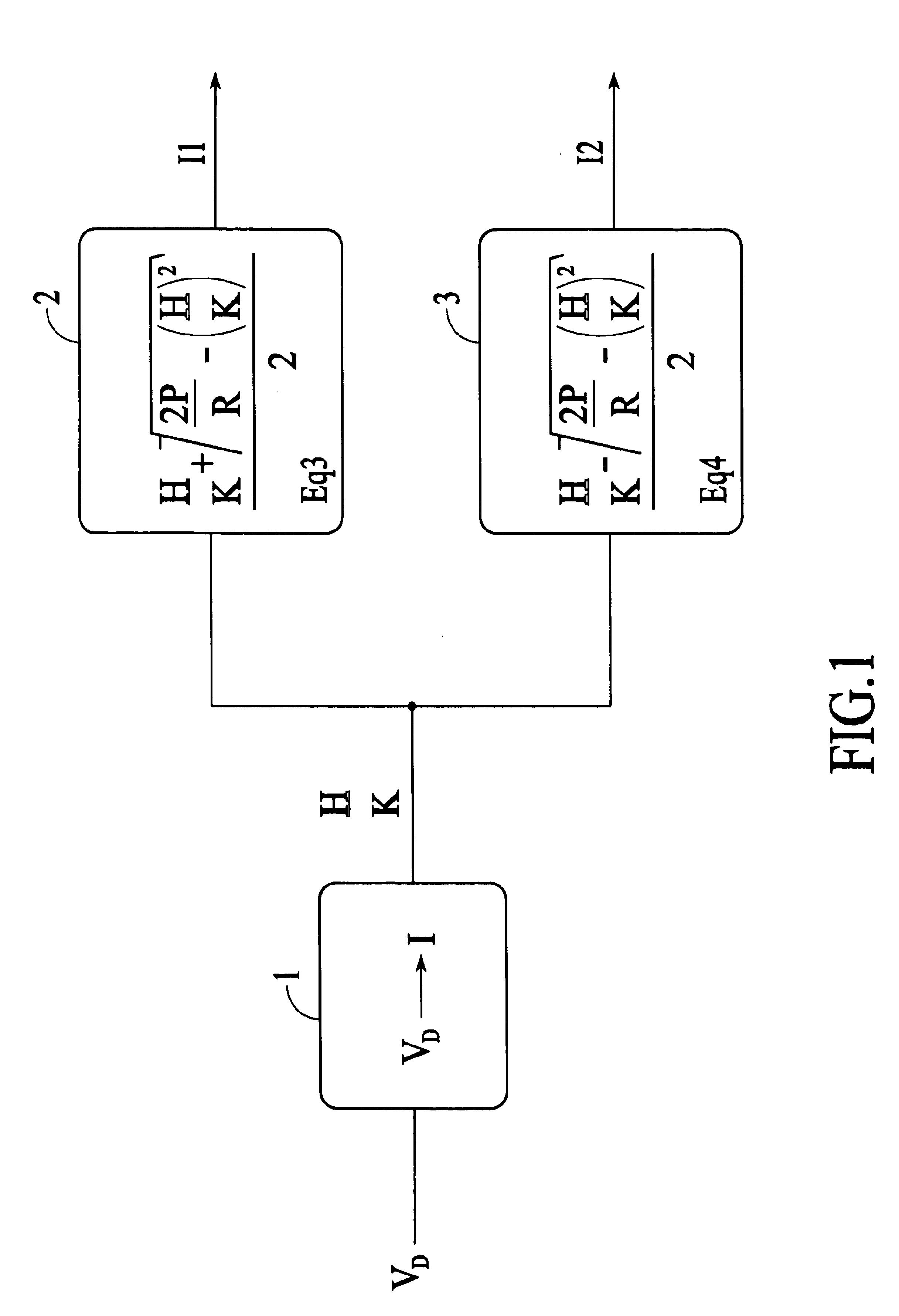
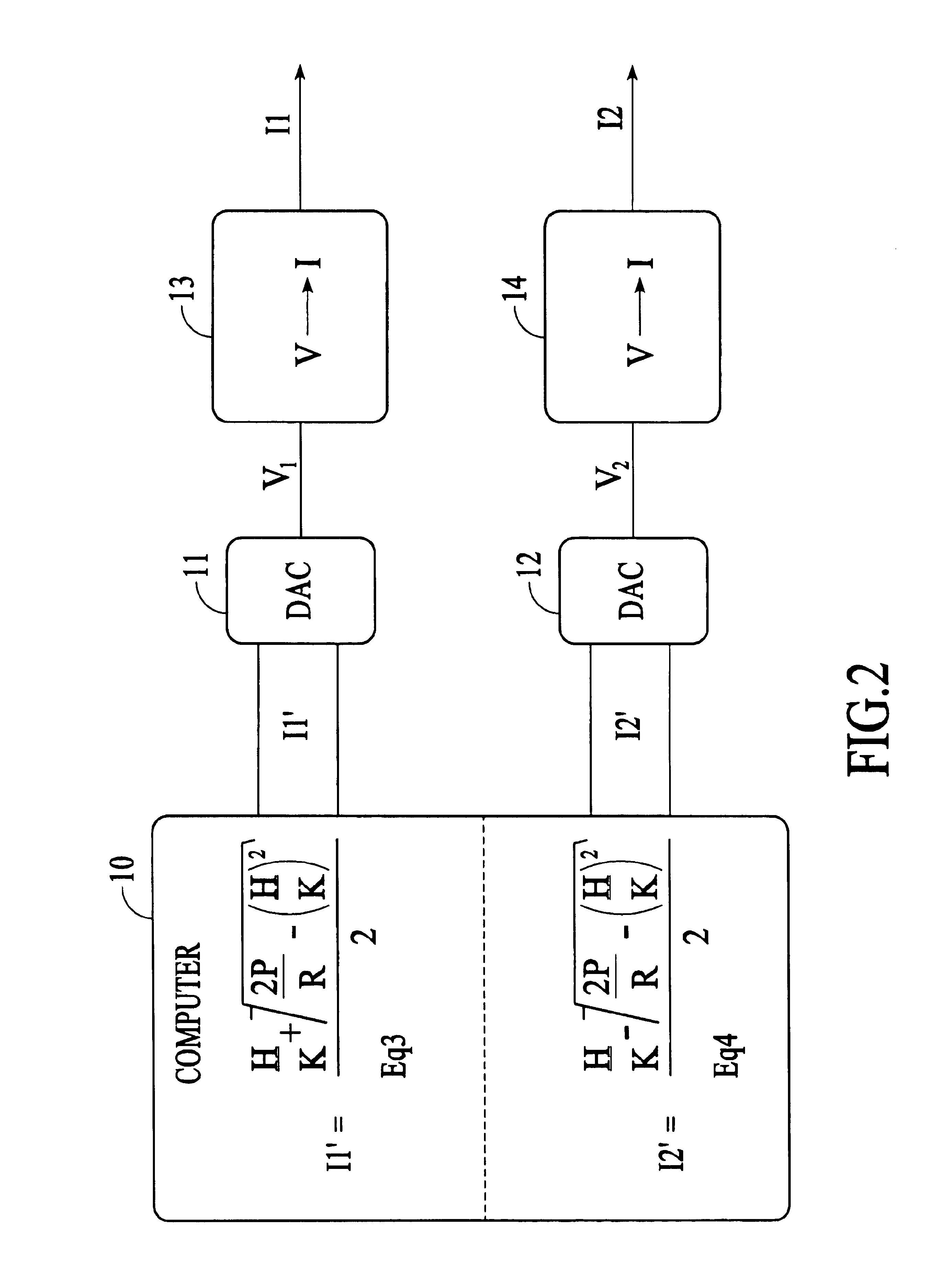
[0046]First, a description will be given of the operating principle of the present invention by referring to FIG. 1 through FIG. 13. A magnetic coil is normally wound with a single continuous strand of conducting material, typically wire. In this invention, a magnetic coil is wound in the normal manner except that multiple strands of parallel conductors or wires are wound through the same path that the single strand would have been wound. For the sake of simplicity we will treat the case where only two conductors are used to construct the coil and the conductors are made of wires. The wires are kept in intimate physical, but not electrical, contact throughout winding such that they are both following the same path at all times. The intimate physical contact assures that heat energy will be transferred uniformly and quickly between the wires. Thus at any given point along the pair of wires, both wires will always be at the same temperature. Preventing electrical contact is necessary ...


PUM

PropertyMeasurementUnit
scan lengthaaaaaaaaaa
resistanceaaaaaaaaaa
magnetic fieldaaaaaaaaaa

Abstract

A coil apparatus is described that incorporates two or more conductors, wound in parallel, following the same path, in intimate physical contact throughout the path but electrically isolated. The current applied to each of the coils can be selected independently. The field generated by the coil, or force on the coil in a magnetic field, is proportional to the algebraic sum of the currents. The power applied to the coil is proportional to the sum of square of the currents. By independently selecting the appropriate current's to apply to each of the conductors, a desired field, or force, can be generated by the coil for any desired power applied to the coil. By judiciously selecting appropriate currents to apply to each of the conductors, a range of fields, or forces, may be selected for which a constant power may be applied to the coil. A constant power enables the coil to operate at a constant temperature.

Description

CROSS-REFERENCE TO RELATED APPLICATION[0001]This invention is based on U.S. Provisional Patent Application Ser. No. 60 / 448,842 filed Feb. 18, 2003 entitled “CONSTANT POWER AND TEMPERATURE COIL” filed in the name of Glenn Henry Martin, Ronald L. Rohde, and John O. H. Niswonger. The priority of this application is hereby claimed and it is hereby incorporated herein by reference thereto.FIELD OF THE INVENTION[0002]The present invention generally relates to generation of a magnetic field, or application of a current within an externally induced magnetic field, while holding the temperature of the current elements at a constant temperature by application of a constant power. More particularly, this invention relates to charged particle beam exposure methods and apparatuses. Even more particularly this invention relates to a charged particle beam exposure method which is suited to achieving a stable, high resolution pattern over a wide range of deflection fields at a high rate of throughp...

Claims


Application Information

Patent Timeline
Patent Type & Authority Patents(United States)
IPC IPC(8): H01F27/08G21K5/04H01F7/20H01J37/147
CPCG21K5/04H01J37/147H01F7/20
Inventor MARTIN, GLENN HENRYROHDE, RONALD LNISOWNGER, JOHN O. H.
Owner MARTIN GLENN HENRY
Features
  • R&D
  • Intellectual Property
  • Life Sciences
  • Materials
  • Tech Scout
  • Unparalleled Data Quality
  • Higher Quality Content
  • 60% Fewer Hallucinations
Learn More