
Curve generating device and method, and program recorded medium

a curve and generating device technology, applied in the direction of static indicating devices, instruments, television systems, etc., can solve the problems of requiring the labor of users in preparing the shape, the processing of contour shapes with respect to respective frames constituting a moving picture is extremely labor-intensive, and the quantity of processing is vast, so as to achieve the effect of preparing contour shapes with higher precision

Inactive Publication Date: 2006-07-18
SONY CORP
View PDF10 Cites 20 Cited by
  • Summary
  • Abstract
  • Description
  • Claims
  • Application Information

AI Technical Summary

Benefits of technology

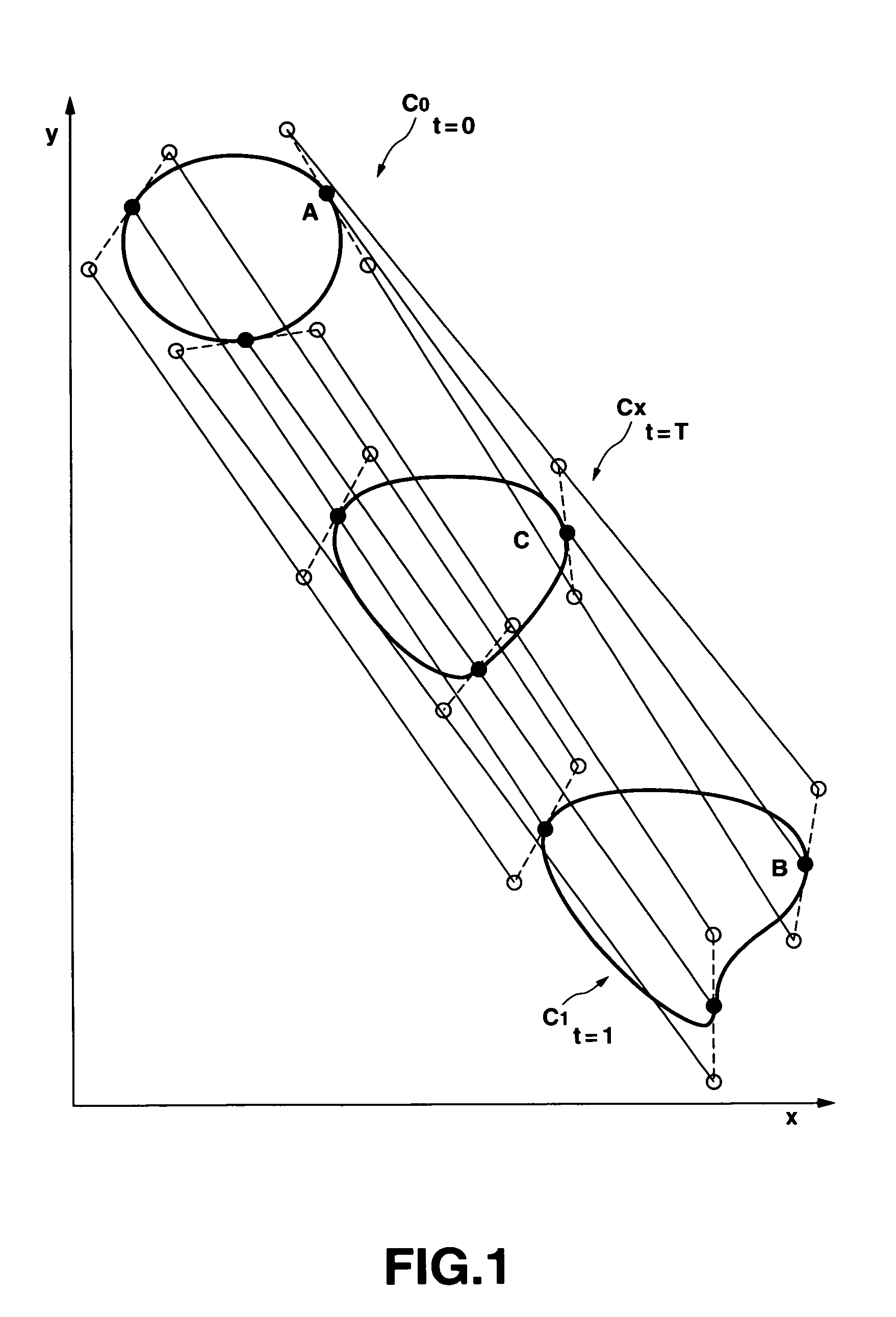
[0014]This invention has been made in view of actual circumstances as described above, and its object is to provide a curve generating apparatus and a curve generating method in which, in the processing for preparing an intermediate shape of two curves, even in the case where the contour shape does not linearly move, it is possible to precisely pursue correspondence points on the contour, thus to prepare contour shapes with higher precision.

Problems solved by technology

For example, in cinemas or television picture images, several hundreds of key signals are required for generating images of several seconds, and the quantity of processing is vast.
This results from the fact that, in the conventional contour extraction processing, processing for preparing contour shapes with respect to respective frames constituting a moving picture is processing that requires extremely much time and labor.
For this reason, there took place the problem that labor of the user was required in preparing the shape, and there took place fine unevenness of the shape because the shape that is prepared discontinuously changes in the time axis direction owing to manual modification.

Method used


Image

  • Curve generating device and method, and program recorded medium
  • Curve generating device and method, and program recorded medium
  • Curve generating device and method, and program recorded medium

Examples


Embodiment Construction

[0055]Preferred embodiments of this invention will now be described in detail with reference to the attached drawings.

[0056]A curve generating apparatus 1 to which this invention is applied is caused to be of a configuration as shown in FIG. 4, for example. This curve generating apparatus 1 is adapted so that a program memory 3, a data memory 4, a frame memory 5, an operation input unit 6, and an external storage (memory) unit 7 are connected to an arithmetic processing unit 2 through a bus 8.

[0057]In the program memory 3, there is recorded a program for executing a curve generating method according to this invention. Namely, the program memory 3 records therein, as a software program, the curve generating method comprising a correspondence point detection step of determining, by using a curve to be generated or processed of the first frame, correspondence points at a second frame corresponding to reference correspondence points set on the curve to be generated of the first frame, a...


PUM


Abstract

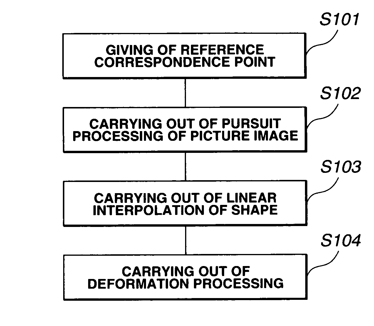
A user gives, as input, two curves at a start time and at an end time and reference correspondence points with respect to the respective curves. Then, a pursuit operation of pursuing a reference correspondence point is carried out with respect to picture images successive in the time axis direction. As a result, positions of reference correspondence points at respective intermediate stages can be determined. Then, interpolation of the shape is carried out. Then, the determined interpolated shape is deformed in correspondence with the determined reference correspondence point. Accordingly, even in the case where a contour shape does not linearly move, it is possible to precisely pursue correspondence points on the contour. Thus, a contour shape with higher precision can be prepared.

Description

TECHNICAL FIELD[0001]This invention relates to a curve generating apparatus and a curve generating method used in CAD (Computer Aided Design), CG (Computer Graphics), etc. that edit a curve indicating contour shape of an object included within a picture image on the computer, and a program recording medium adapted so that a program relating to the curve generating method is recorded.BACKGROUND ART[0002]Hitherto, there are many instances where contour extraction processing for extracting a contour shape of an object included in plural picture image data constituting a moving picture image are used in the field of picture image processing, e.g., CAD, CG technologies, etc. Among these picture image processing methods, when picture image synthesis processing is carried out, there is the processing that generates key signals from the contour shape of the object, and it is important to generate precise or accurate key signals, i.e., precise contour shape. In this case, the key signal is i...

Claims


Application Information

Patent Timeline
IPC IPC(8): G06T11/20H04N5/275G06F17/17G06T3/40G06T13/00G06T13/80
CPCG06F17/17G06T3/0093G06T13/80G06T11/203G06T2210/44G06T3/18
Inventor SHIMADA, SHIGEHIROTSUKAMOTO, JUNICHITOTSUKA, TAKASHI
Owner SONY CORP
Learn More