Optical deflector

a deflector and optical technology, applied in the field of optical deflectors, can solve the problems of signal delay in the detection circuit, timing errors, and inability to control the angle of deflection and keep it to a constant value, and achieve the effect of accurate control of the operation of the deflector

Inactive Publication Date: 2006-07-18
CANON KK
View PDF11 Cites 1 Cited by
  • Summary
  • Abstract
  • Description
  • Claims
  • Application Information

AI Technical Summary

Benefits of technology

[0012]The inventor of the present invention came up with an idea different from that of the inventor of the invention disclosed in Japanese Patent Application Laid-Open No. 2001-305471. More specifically, it is the object of the present invention to make it possible to very accurately control the operation of a deflection means, or an actuator, without using a detection means for detecting the time when a beam of light passes by a predetermined angle of deflection, or actuator, in such a way that it is not affected by changes of environmental temperature of the deflection means and the detection circuit.

Problems solved by technology

The invention disclosed in the above patent document paid attention to the fact that the resonance period of an electromagnetic actuator normally drifts with temperature and time and hence, if an electric current having a predetermined, constant resonance frequency is continuously supplied to the planar coil, there arises a problem that it is not possible to control the angle of deflection and keep it to a constant value with temperature change and time lapse.
With the method of detecting the time when the actuator passes by a predetermined angle of deflection gives rise to a signal delay in the detection circuit due to changes of environmental temperature.
Additionally, timing errors can occur when gauging the change with time of the angle of deflection and detecting the time on the basis of the gauged change because the detection timing can be shifted by signal noises and offsets.
Thus, the problem of signal delays and timing errors arises when accurately controlling an actuator by such a method of detecting the time when the actuator passes by a predetermined angle of deflection.

Method used


Image

  • Optical deflector
  • Optical deflector
  • Optical deflector

Examples


first embodiment

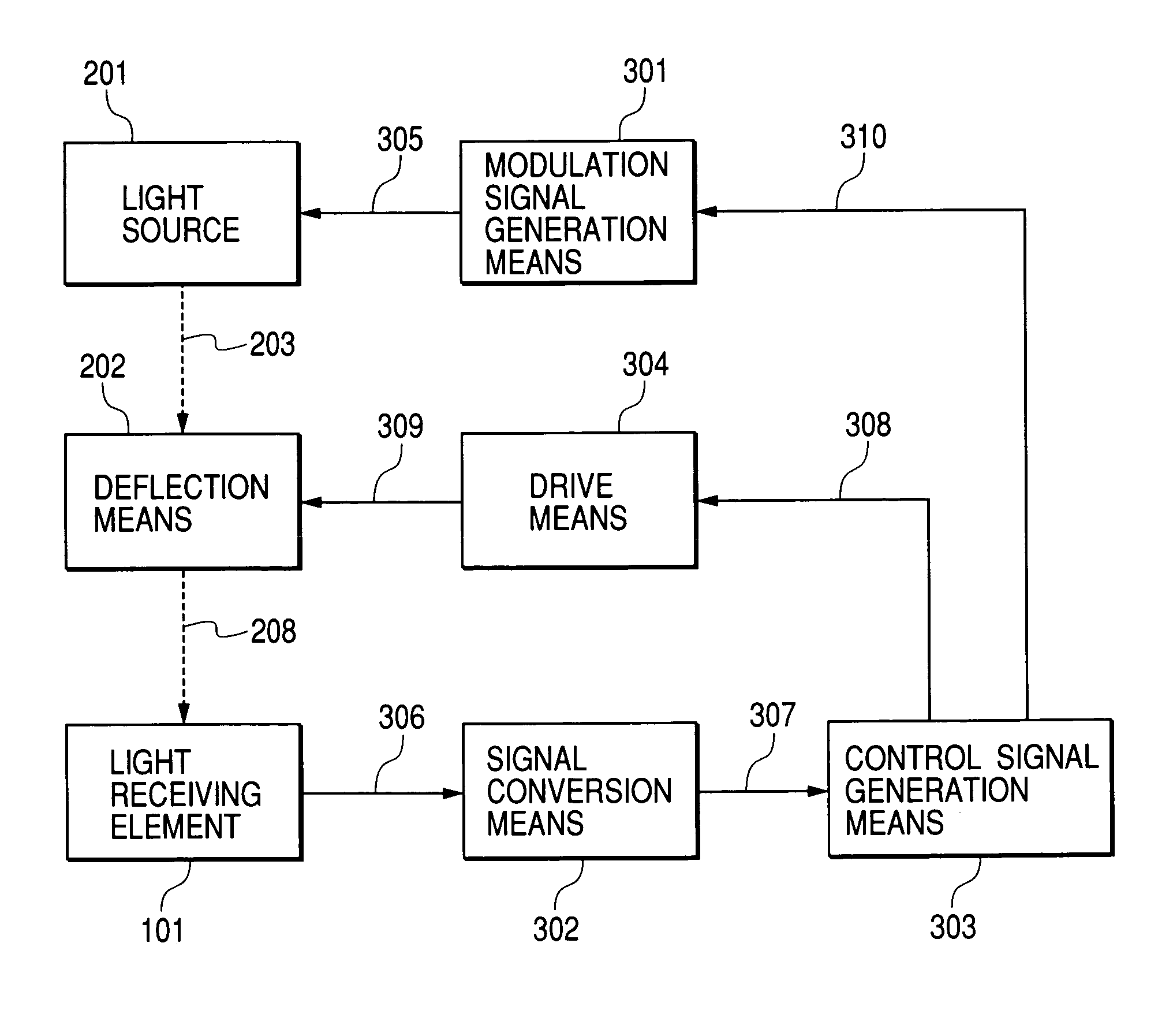
[0035]The inventor of the present invention came to have an idea of utilizing deflected beams of light that are emitted from a light source and deflected to reciprocate for scanning by a deflection means that also reciprocates (swings), for controlling at least either the light source or the deflection means.

[0036]More specifically, according to the invention, deflected beams of light moving forward and moving backward are detected by a light receiving element and either the deflection means or the light source is controlled by way of a control means in such a way that the distance (displacement) between the position of the forwardly moving deflected beam of light and that of the backwardly moving deflected beam of light, each at a given clock time, shows a predetermined value.

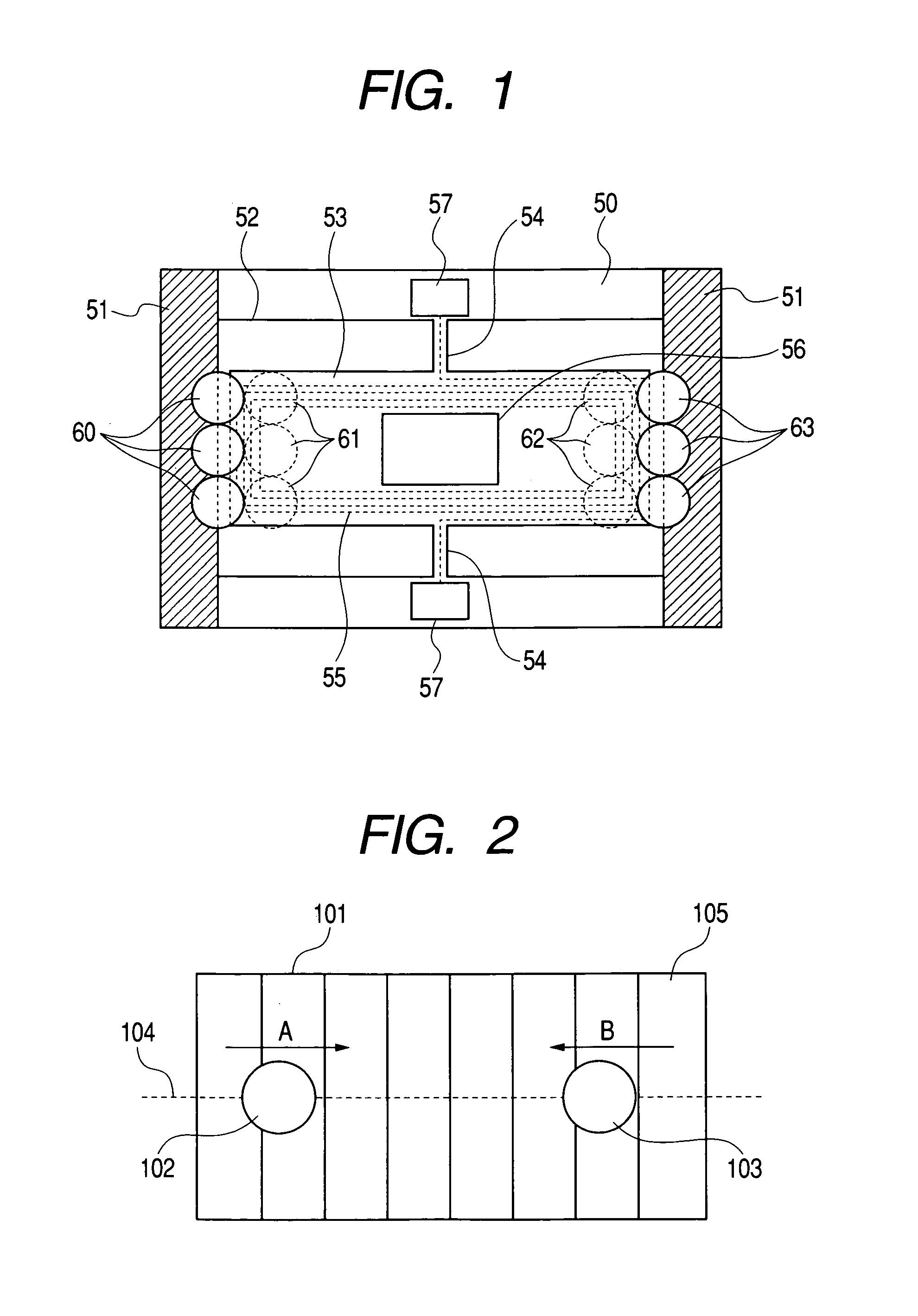
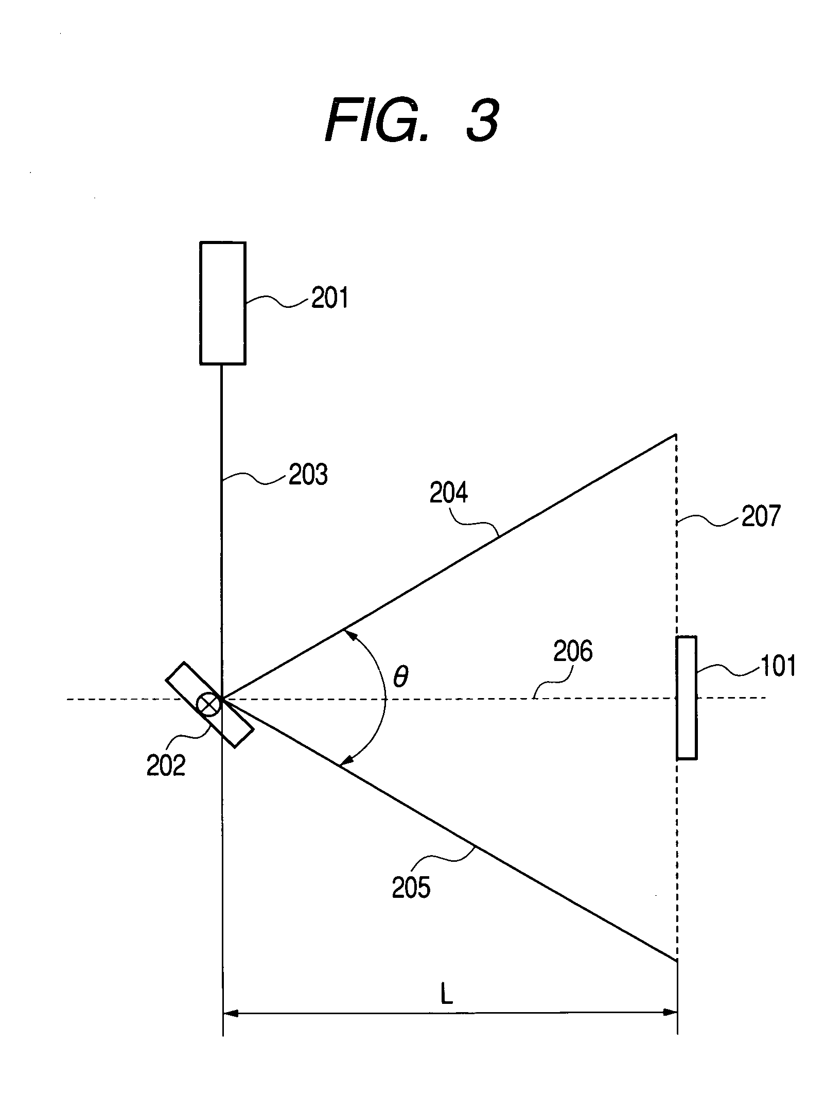
[0037]FIG. 2 is a schematic illustration of scanning of beams of light that are deflected (reflected) by the deflection means of the first embodiment of optical deflector so as to reciprocate on a light receiv...

second embodiment

[0095]This embodiment differs from the first embodiment in terms of the method for identifying the position (central position) of each of the modulated and deflected beams of light (modulated spots) on the light receiving element 101 comprising a plurality of light receiving regions 105. Otherwise, this embodiment is identical with the first embodiment.

[0096]FIGS. 6A, 6B and 6C are schematic illustrations of the second embodiment.

[0097]FIG. 6A shows the positional relationship of the position on the light receiving element 101 where a modulated spot is formed and the plurality of light receiving regions 105. Note that the scanning direction is horizontal on FIG. 6A. For the purpose of simplicity, assume here that there is a single modulated spot on the light receiving element 101. For the purpose of the invention, the process that is described below may be repeated for the number of times that is equal to the number of spots that is involved in the optical deflector.

[0098]FIG. 6B is...

third embodiment

[0106]This embodiment differs from the first and second embodiments in that the light receiving element 101 has a plurality of light receiving regions 105 that are two-dimensionally arranged. Otherwise, this embodiment is identical with the first and second embodiments.

[0107]FIG. 7 is a schematic illustration of a plurality of light receiving elements that the light receiving element of the third embodiment includes.

[0108]As shown in FIG. 7, the light receiving element 101 has a plurality of light receiving regions 105 that are arranged two-dimensionally. In other words, the light receiving regions 105 have a square profile and are arranged in rows and columns.

[0109]When a plurality of light receiving regions 105 are arranged two-dimensionally as in the case of this embodiment, the distribution of quantity of light of a modulated spot can be detected two-dimensionally so that the profile of the modulated spot can be grasped accurately and a large quantity of data can be used for sel...


PUM

PropertyMeasurementUnit
angle of deflectionaaaaaaaaaa
resonance frequencyaaaaaaaaaa
diameteraaaaaaaaaa

Abstract

An optical deflector comprises a control means for controlling at least either a light source or a deflection means adapted to gauge the distance between the position of a deflected beam of light moving on a light receiving element in one direction and the position of another deflected beam of light moving on the light receiving element in the opposite direction and control the distance so as to make it agree with a predetermined value. Thus, the optical deflector can very accurately control the operation of the deflection means in such a way that it is not affected by changes of environmental temperature of the deflection means and the detection circuit, because a detection means for detecting the time when a beam of light passes by a predetermined angle of deflection of the deflection means is not used.

Description

BACKGROUND OF THE INVENTION[0001]1. Field of the Invention[0002]This invention relates to an optical deflector having a deflection means for deflecting light.[0003]2. Related Background Art[0004]FIG. 1 of the accompanying drawings illustrates a galvano-mirror as an example of optical deflector that is driven by electromagnetic force. A mirror is arranged on a movable section, which is supported by a main body by way of a pair of torsion bars so that it may be rotated relative to a central axis. In FIG. 1, reference symbol 50 denotes a silicon substrate and reference symbols 51 and 52 respectively denote an upper glass substrate and a lower glass substrate. There are also shown a movable plate 53, a pair of torsion bars 54, a planar coil 55, a total reflection mirror 56, a pair of electrode terminals 57 and permanent magnets 60 through 63. The illustrated optical deflector is of the electromagnetic type that is driven by causing a drive current to flow through the planar coil 55 and ...

Claims


Application Information

Patent Timeline
Patent Type & Authority Patents(United States)
IPC IPC(8): G02B26/08G02B26/10G02B26/12G02B27/00
CPCG02B26/0816G02B27/0031G02B26/101Y10S359/90
Inventor KANDORI, ATSUSHIMAJIMA, MASAO
Owner CANON KK
Why Eureka
Try Eureka