
Method for creating facies probability cubes based upon geologic interpretation

a probability cube and facies technology, applied in the direction of seismology for waterlogging, using reradiation, instruments, etc., can solve the problems of both simulation methods failing to account for valuable information, failing to adequately model reservoirs, and giving models a very limited control on the continuity and the geometry of simulated facies, etc., to achieve the effect of reducing complexity and being readily changed

Active Publication Date: 2006-07-18
CHEVROU USA INC
View PDF22 Cites 64 Cited by
  • Summary
  • Abstract
  • Description
  • Claims
  • Application Information

AI Technical Summary

Benefits of technology

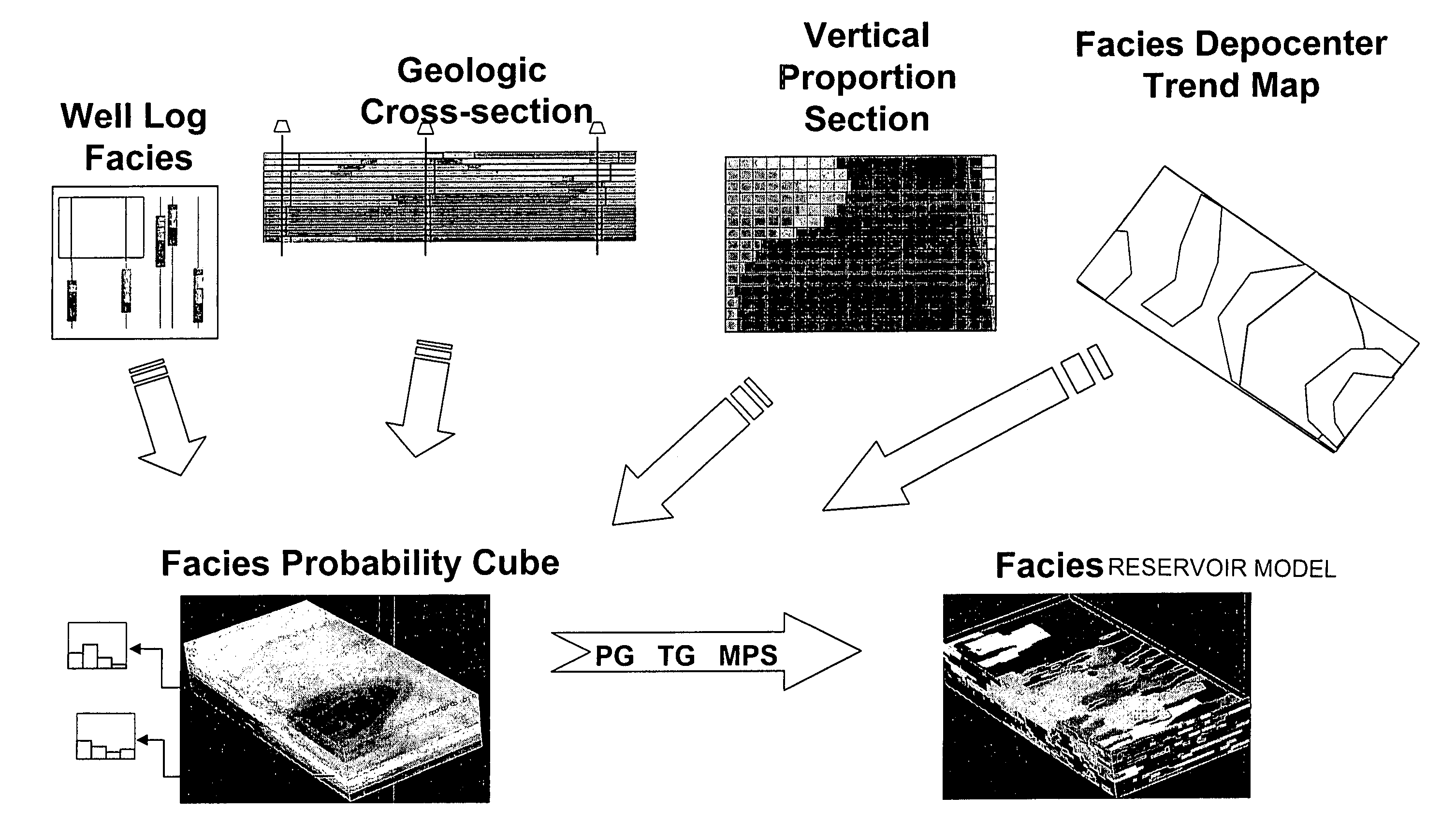
[0020]The method for building the facies probability cubes also may account for cases where there are dominant or else a minimal horizontal facies proportion for a column of cells. A user may define upper and lower thresholds for these facies proportions. In the event the proportion of a facies falls below or above the thresholds, the integration of the vertical and horizontal facies data will utilize specially developed weighted facies proportion data. This data accounts for the low or high probability of finding a particular facies in a column of cells.
[0021]A method for generating horizontal facies proportion data for a S-grid is also described. This data reflects the areal distribution of facies within the S-grid. The grid includes layers and columns of cells. Boundaries are defined-on an areal depocenter map to delineate depocenter regions in which respective facies are likely to occur within the S-grid. Ideally, these depocenter regions are estimated generally independently of one another to reduce the complexity that is otherwise incurred when trying to simultaneously account for the presence of all facies in a S-grid. Horizontal facies proportion data is generated for the columns of cells based on the defined boundaries of the depocenter regions with the proportion of each facies ranging from a maximum value at a depocenter of a respective facies depocenter region to a minimum value located laterally from the depocenter. Preferably, a transition filter is applied to a depocenter boundary to transition the facies probabilities from maximum to minimum values.
[0023]It is another object to use a transition filter to calculate horizontal facies proportion data from defined boundaries for depocenter regions wherein the transition filter can be readily changed so that multiple facies probabilities cubes can be quickly created and evaluated.

Problems solved by technology

These variogram-based simulation techniques are known to give to a modeler a very limited control on the continuity and the geometry of simulated facies.
The techniques may provide reasonable predictions of the subsurface architecture in the presence of closely spaced and abundant data, but they usually fail to adequately model reservoirs with sparse data collected at a limited number of wells.
Both simulations methods fail to account for valuable information that can be provided only by geologist / geophysicist's interpretation of the reservoir's geological setting based upon their knowledge of the depositional geology of the region being modeled.
Making simultaneous estimates of facies locations and probabilities that are highly dependent upon one, either through digitization or through estimating equations, are complex and challenging.
Such methods make it difficult to rapidly create numerous probability cubes based on different geologic interpretations and assumptions of how the facies are distributed in a S-grid.
Furthermore, algorithms used to combine vertical and map facies trend information to produce facies probability cubes can produce less than optimal estimates of the probabilities.

Method used


Image

  • Method for creating facies probability cubes based upon geologic interpretation
  • Method for creating facies probability cubes based upon geologic interpretation
  • Method for creating facies probability cubes based upon geologic interpretation

Examples


Embodiment Construction

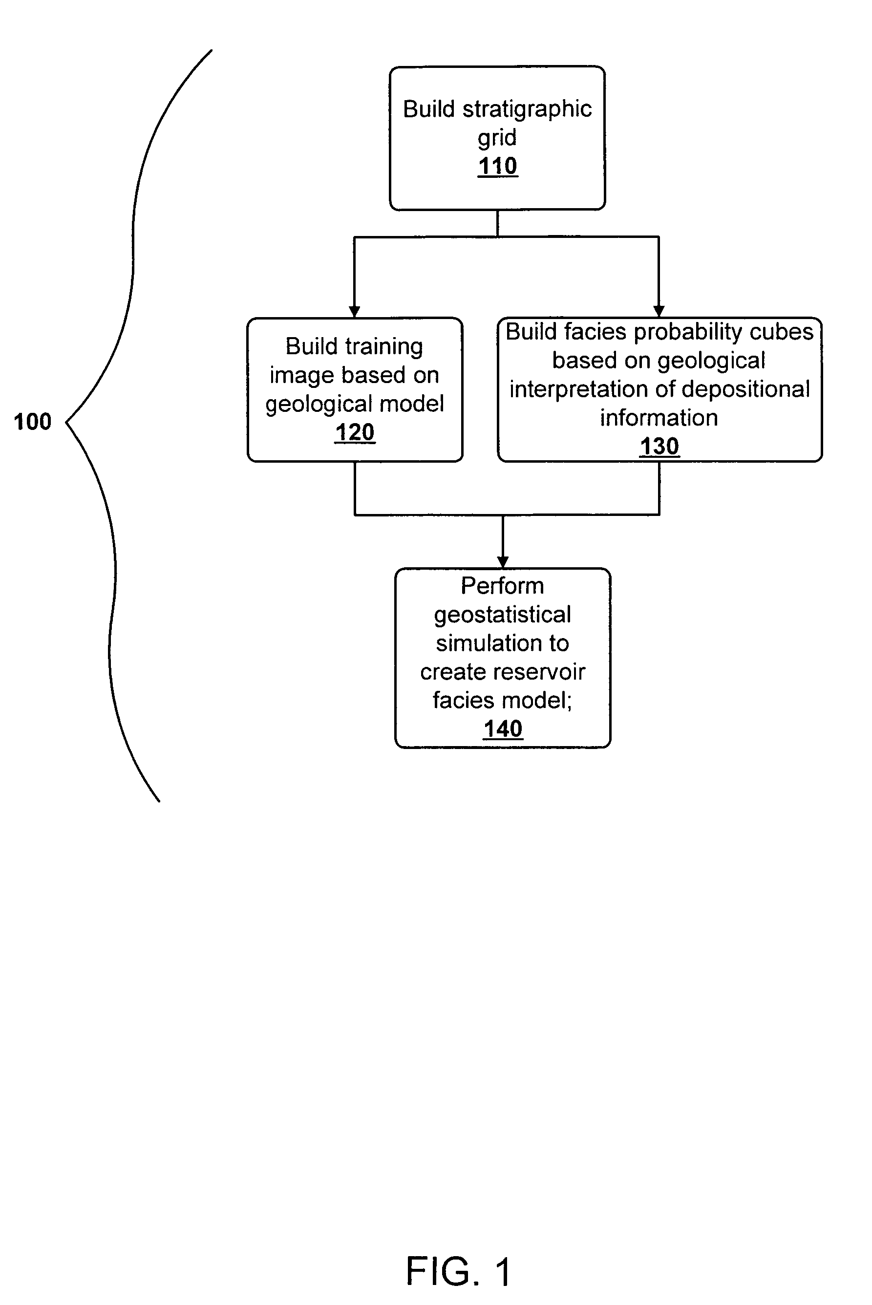
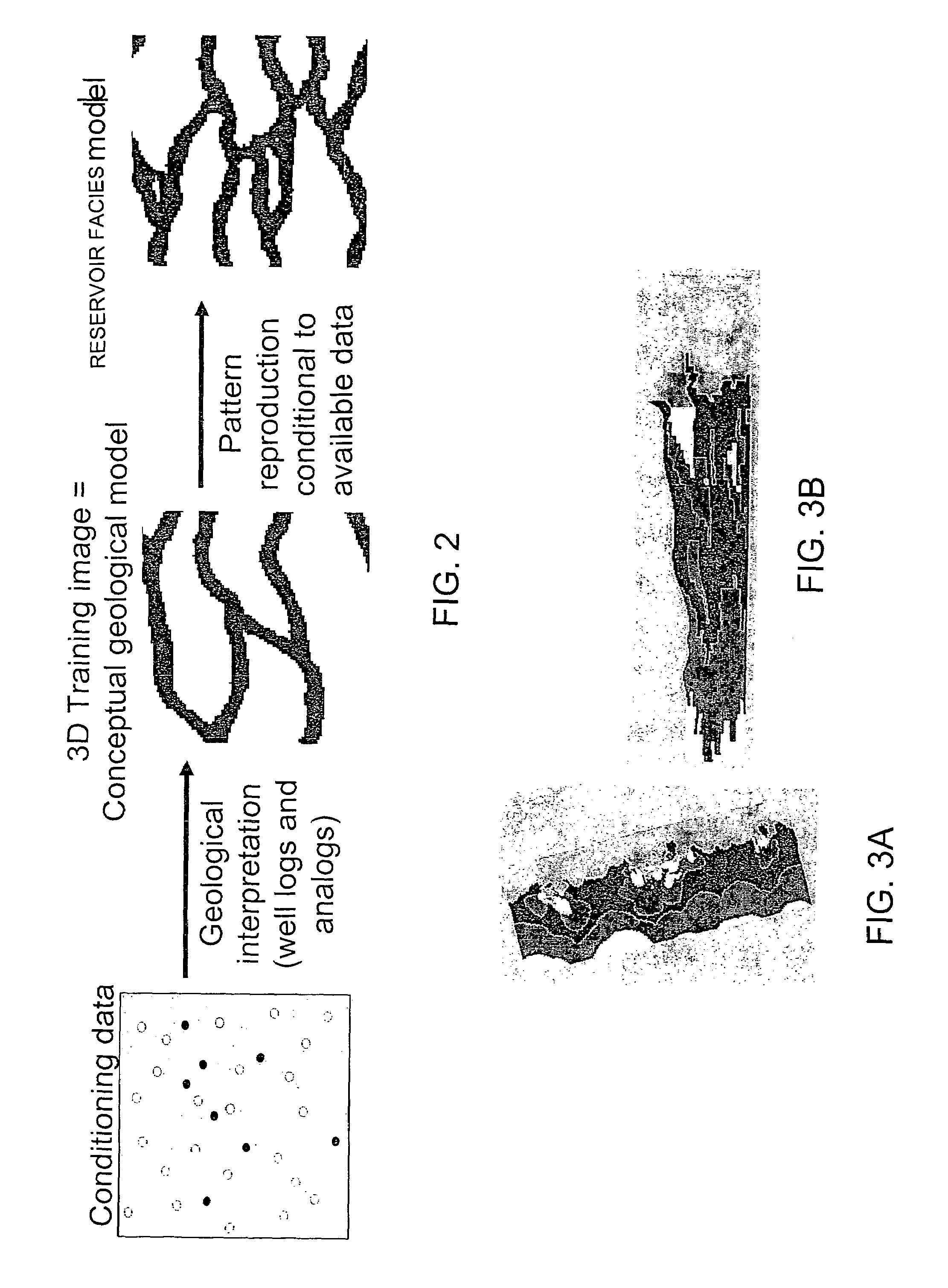
[0045]FIG. 1 shows a workflow 100, made in accordance with a preferred embodiment of the present invention, for creating a reservoir facies model. In particular, the workflow uses a training image, in conjunction with a geologically-interpreted facies probability cube as a soft constraint, in a geostatistical simulation to create a reservoir facies model.

[0046]A first step 110 in the workflow is to build a S-grid representative of a subsurface region to be modeled. The S-grid geometry relates to reservoir stratigraphic correlations. Training images are created in step 120 which reflect the interpreted geometry of each facies and the associations among facies. A geologically-interpreted facies probability cube is then created in step 130. This facies probability cube captures information regarding the absolute spatial distribution of facies in the S-grid based upon geologic depositional information and conceptualizations. The facies probability cube ideally honors local facies distri...


PUM


Abstract

A method for creating a facies probability cube is disclosed. A S-grid containing facies is first created. The grid includes layers of cells and columns of cells. Vertical facies proportion data for the layers of cells is derived from sources such as well data, conceptual vertical geologic sections and graphs describing the proportion of facies found in each of the layers. Areal depocenter maps are created which have defined boundaries to create depocenter regions in which respective facies are likely to occur. Ideally, the boundaries for the depocenter regions for each of the facies are sequentially and independently defined. Horizontal or map facies proportion data are generated for the columns of cells preferably by filtering the depocenter regions so that the proportion of each of the facies ranges from a maximum value to a minimum value. The vertical and horizontal facies proportion data are then integrated to create a facies probability cube in which the cells are assigned probabilities for the occurrence of facies.

Description

CROSS-REFERENCE TO RELATED PATENT APPLICATIONS[0001]This application incorporates by reference all of the following co-pending applications:[0002]“Method for Making a Reservoir Facies Model Utilizing a Training Image and a Geologically Interpreted Facies Probability Cube,” Ser. No. 10,923,316, filed herewith.[0003]“Multiple-Point Statistics (MPS) Simulation with Enhanced Computational Efficiency,” Ser. No. 10 / 923,336, filed herewith.FIELD OF THE INVENTION[0004]The present invention relates generally to methods for constructing reservoir facies models, and more particularly, to methods for creating facies probability cubes to be used in geostatistical simulations to create reservoir facies models.BACKGROUND OF THE INVENTION[0005]Reservoir flow simulation typically uses a 3D static model of a reservoir. This static model includes a 3D stratigraphic grid (S-grid) commonly comprising millions of cells wherein each individual cell is populated with properties such as porosity, permeabili...

Claims


Application Information

Patent Timeline
Patent Type & Authority Patents(United States)
IPC IPC(8): G01V1/28
CPCG01V1/30G01V2210/661
Inventor THORNE, JULIAN ARTHURLEVY, MARJORIE E.HARDING, ANDREW WILLIAMXIE, DEYI
Owner CHEVROU USA INC
Learn More