Control for a graphical user interface supporting coupled variables and method of operation thereof

US7080324B1Inactive Publication Date: 2006-07-18AGILENT TECH INC

Image

  • Control for a graphical user interface supporting coupled variables and method of operation thereof
  • Control for a graphical user interface supporting coupled variables and method of operation thereof
  • Control for a graphical user interface supporting coupled variables and method of operation thereof

Examples


Embodiment Construction

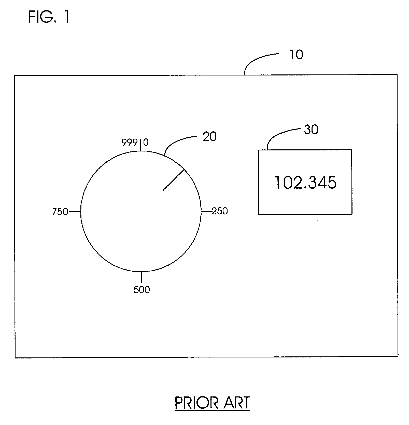
[0020]FIG. 1 shows a prior art controller 10 (e.g., for use with a rotary pulse generator or stereo volume control) having a graphical representation of a knob 20 and a display box 30. To operate the prior art controller 10, the user clicks the knob 20 with a conventional cursor control device (e.g., the PC mouse), and while holding the PC mouse button, rotates the knob 20 using the PC mouse until the desired value is displayed in the display box 30. Alternatively, the user can click on the display box 30 and directly input the desired value (e.g., by highlighting the display box 30 with the PC mouse, and typing a value using a conventional keyboard).

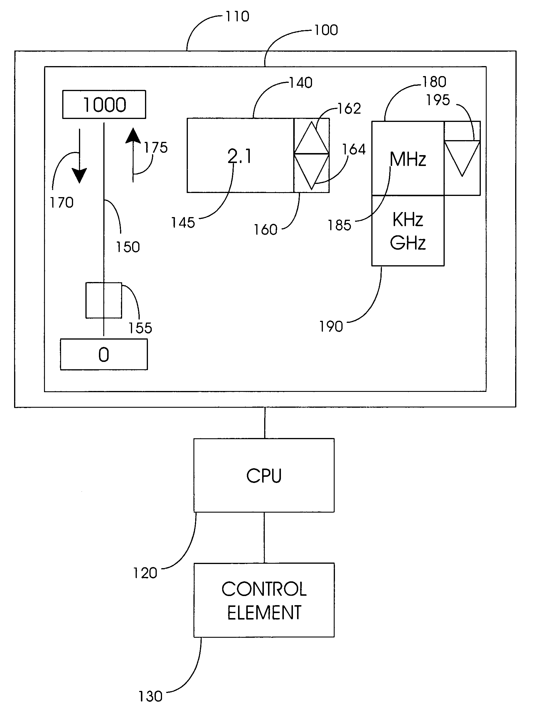
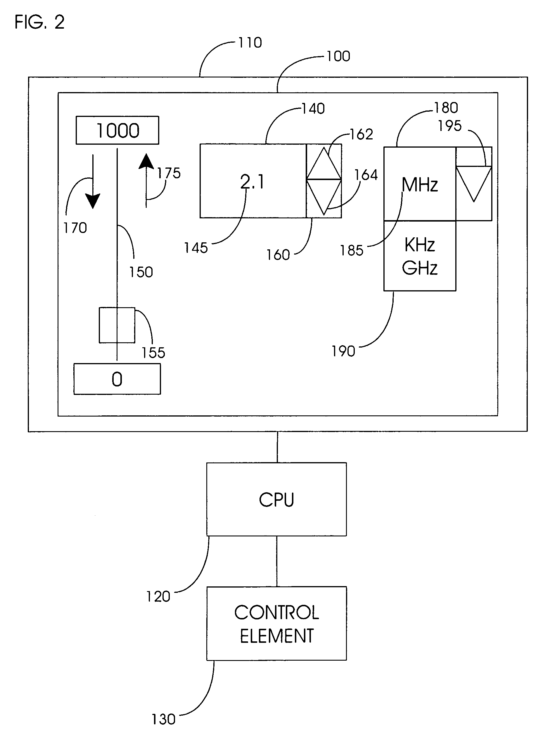
[0021]FIG. 2 shows a variable control 100 of the present invention. The variable control 100 is displayed through a graphical user interface or GUI 110 (e.g., the Microsoft WINDOWS® Operating System displayed through a conventional display device such as a computer monitor, television, LCD, etc.) and connected through a conventional CPU...


PUM


Abstract

A variable control displayed through a graphical user interface and linked to a control element. The variable control has graphical representations of readily identifiable and easy to use controls. These controls include at least one text box to display a value. The displayed value can be set by default, or to show the current state of the control element. The variable control also includes at least one range box for assigning a range unit that corresponds to the text box. The variable control also includes a slider control that is linked to the text box and is used to make coarse adjustments to the value displayed in the text box. A spinner is also linked to the text box and is used to make fine adjustments to the displayed value. In a preferred embodiment, the user can select a digit or several digits within the displayed value and adjust only the user-selected digit or digits. Also in a preferred embodiment, the range box automatically updates the range unit when the displayed value is adjusted beyond a predetermined range limit.

Description

FIELD OF THE INVENTION[0001]The invention pertains to a control for display through a graphical user interface supporting coupled variables updated automatically when a coupled variable changes, and a method of operation of the control to make coarse and fine adjustments to a control element.BACKGROUND OF THE INVENTION[0002]Equipment controls (e.g., stereo, pulse generator, and other electronic equipment knobs) have been simulated for display through a graphical user interface (GUI) on a computer monitor or other display device. For example, graphical representations of stereo volume control knobs or rotary pulse generator (RPG) frequency setting knobs are conventionally displayed through the GUI as round knobs to minimize physical knobs. To adjust the settings (e.g., the volume or frequency), the user positions the cursor on the graphical representation of the knob using a PC mouse, touch pad, or other suitable cursor control device, and then clicks and holds down the PC mouse butt...

Claims


Application Information

Patent Timeline
18 Jul 2006
Publication
US7080324B1
IPC
G06F3/00; G06F3/048; G06F3/033; G06F3/0482; G06F3/0484
CPC
G06F3/04847; Y10S715/974
Inventors
NELSON, ALAN C.; RYLES, JANICE G.