Wear assembly for excavator digging edge

a technology for digging edge and wear assembly, which is applied in the direction of manufacturing tools, connections, constructions, etc., can solve the problems of loosening the lock, affecting the service life of the wear member, so as to reduce the application force and stress on the lip, the effect of enhancing the support of the rails and reducing the maintenance requirements

Inactive Publication Date: 2006-07-25
ESCO GRP LLC
View PDF53 Cites 63 Cited by
  • Summary
  • Abstract
  • Description
  • Claims
  • Application Information

AI Technical Summary

Benefits of technology

[0007]In accordance with one aspect of the invention, the wear member is secured to the lip of an excavator (e.g., an excavating bucket) in a stable and balanced manner without the formation of a through-hole in the lip. In a preferred construction, the wear assembly includes a boss and a wear member that cooperate to define a passage forward of the front edge face of the lip for receiving the lock. In this way, the lock can be engaged on each side of the central plane of the lip. The lip can be maintained as an imperforate member for greater strength and durability.
[0008]In another aspect of the present invention, the lip of the excavator includes an inner face, an outer face and a front edge face. The front edge face includes a plurality of spaced scallops. The scallops cooperate with the wear assembly to permit a through-hole for the lock to be formed forward of the lip without undue forward projection of the boss. The scallops are preferably formed by a concave wall that extends no more than about 180 degrees about an axis that is generally perpendicular to the lip. In this way, the scallop can provide the desired space for the lock without causing significant weakening of the lip.
[0011]In another aspect of the invention, the boss includes a body that extends along one of the faces of the lip. Rails extend along opposite sides of the boss to cooperate with a complementary structure on the wear member to hold the wear member in place. A brace extends laterally beyond at least part of the body and is fixed to the rails to provide enhanced support to the rails.
[0012]In one other aspect of the invention, the boss includes a body that extends along one of the faces of the lip and a brace at a rear end of the body. The brace extends beyond the body in a transverse direction to define a front bearing face against which a rear wall of the wear member can abut. In this way, the applied forces and stresses on the lip can be reduced to thereby lessen the maintenance requirements and lengthen the usable life of the lip.
[0013]In another aspect of the invention, the boss is formed with a raised deflector that tends to deflect earthen material away from the wear member when the excavator is reversed. In the preferred construction, the deflector is formed at the rear end of and extends farther from the lip than the forward portions of the boss to be juxtaposed to the rear wall of the wear member. An inclined deflector face is preferably formed to reduce the forces applied to the deflector under reverse loading.

Problems solved by technology

Excavating buckets and other excavating equipment are typically subjected to harsh conditions.
However, under load, the legs of the wear member can shift and cause loosening of the lock and possible loss of the wear member.
In addition, the formation of a hole in the lip weakens the lip and its ability to effectively resist the large loads applied as the lip is forced into the ground.
While these constructions avoid weakening the lip with a through-hole, they place very large loads on the lateral boss, and thus, can only be reliably used in low stress environments.
While this is adequate for most applications, this arrangement does orient the lock in an off-center relationship relative to the lip and thus engenders increased vertically oriented stresses on the legs of the wear member as well as the lip.
However, this construction requires more steel and twice as many bosses and locks for the attachment of each wear member.

Method used


Image

  • Wear assembly for excavator digging edge
  • Wear assembly for excavator digging edge
  • Wear assembly for excavator digging edge

Examples


Embodiment Construction

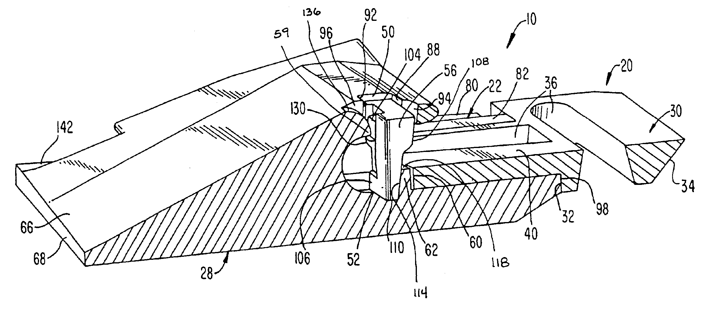
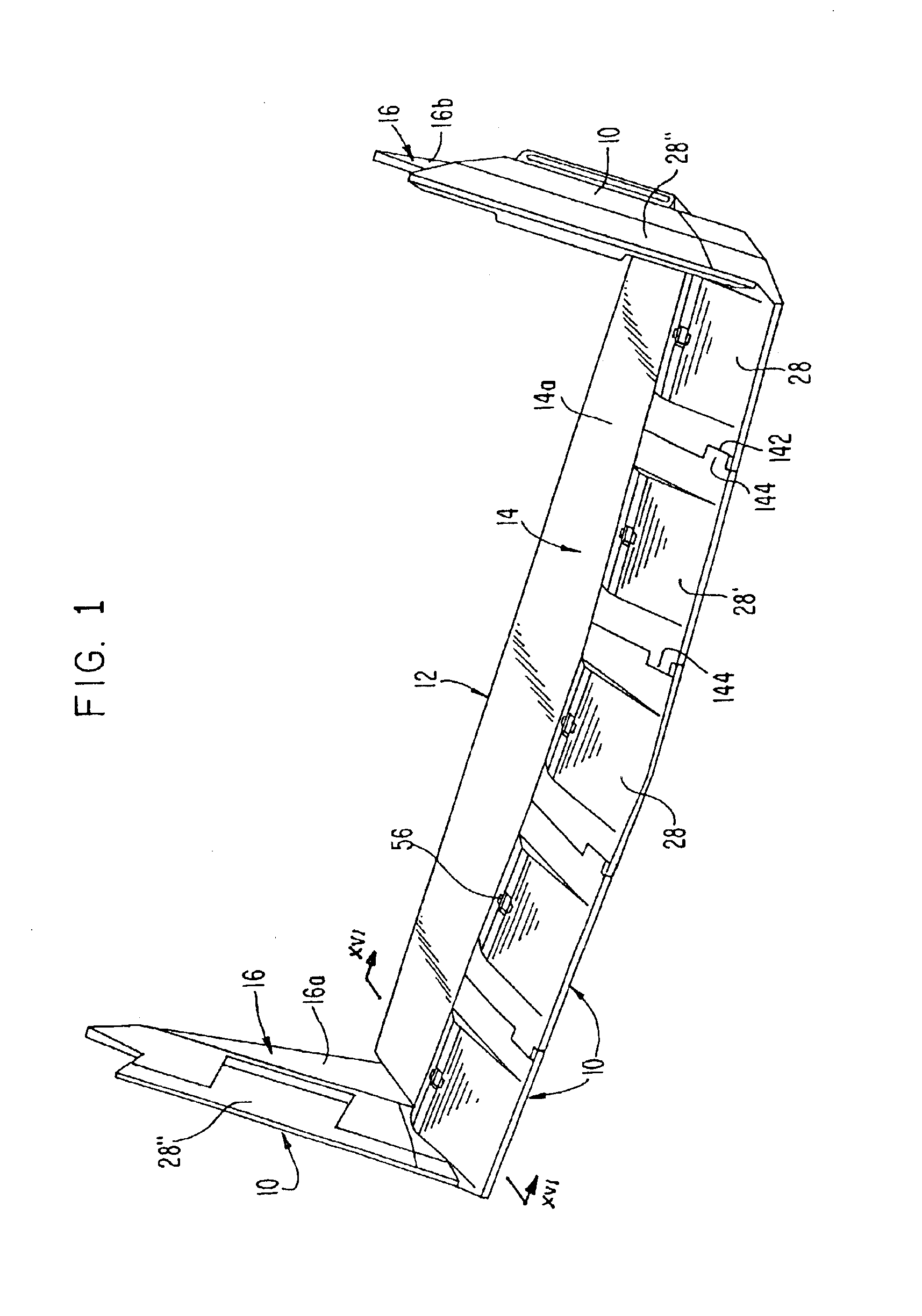
[0033]In accordance with the present invention, a wear assembly 10 is provided for attachment along the digging edge of a lip of an excavator. The invention is discussed below in terms of the attachment of a shroud to the lip of a load-haul-dump (LHD) bucket. However, the invention is not limited to the attachment of a shroud or an LHD bucket. The invention could be used to secure other wear members to other excavators, and even to other equipment where the edge is subject to heavy loading and wear as in an excavating environment.

[0034]The invention is at times discussed in terms of relative terms, such as up, down, right, left, vertical, horizontal, etc. for the sake of easing the description. These terms are to be considered relative to the orientation of the elements in FIG. 1 (unless otherwise noted), and are not to be considered limitations on the invention. As can be appreciated, the wear member can be used and oriented in a variety of ways.

[0035]Lip 12 forms the front digging...


PUM


Abstract

A wear assembly that includes a wear member and a boss to define an opening for receiving a lock forward of the front edge face of the lip which can mount the wear member in a stable and balanced manner without a through-hole in the lip. The wear member includes an aperture and a rib to define bearing faces on opposite sides of a central plane of the lip. The boss includes rails to hold the wear member in place, and a brace at the rear end, which supports the rails on the boss, abuts the rear of the wear member to reduce the loading on the lip, and deflects earthen material away from the wear member under reverse loading.

Description

FIELD OF THE INVENTION[0001]The present invention pertains to a wear assembly for protecting the front edge of a structure subjected to wear, and is particularly suited for use along the front digging edge of an excavating bucket or the like.BACKGROUND OF THE INVENTION[0002]Excavating buckets and other excavating equipment are typically subjected to harsh conditions. A series of wear members are usually provided to protect the digging edges from premature wear. Wear members have been secured to the digging edge in many different ways.[0003]For example, in U.S. Pat. No. 4,570,365 to Bierwith, the wear members are secured to the lip of the bucket by the use of a wedge and spool lock arrangement that is fit through a hole in the lip spaced from the front edge. In this arrangement, the spool pinches the rear parts of the wear member against the inner and outer faces of the lip as the wedge is driven into the hole. However, under load, the legs of the wear member can shift and cause loos...

Claims


Application Information

Patent Timeline
Patent Type & Authority Patents(United States)
IPC IPC(8): E02F9/28E02F3/815
CPCE02F3/8152E02F9/2841E02F9/2825E02F9/2858E02F9/2883Y10T403/7079E02F3/36E02F9/28
Inventor JONES, LARREN F.
Owner ESCO GRP LLC
Why Eureka
Try Eureka