Torque controlled pump protection with mechanical loss compensation

a technology of mechanical loss compensation and torque control, which is applied in the direction of pump parameters, positive displacement liquid engines, fluid couplings, etc., can solve the problems of reducing flexibility during field setup, adding cost and complexity to the drive system, and not including logic that would provide protection against undesirable operating conditions. , to achieve the effect of expanding the operating speed rang

Active Publication Date: 2006-07-25
ITT MFG ENTERPRISES LLC
View PDF14 Cites 91 Cited by
  • Summary
  • Abstract
  • Description
  • Claims
  • Application Information

AI Technical Summary

Benefits of technology

[0016]In operation, the algorithm for the control logic compensates the original torque input data for the current operating speed according to the square of the speed change and compensates for mechanical losses, such as seal and bearing losses, which vary linearly with the speed change.
[0019]One advantage of the torque controlled pump protection technique with mechanical loss compensation, according to the present invention, is that it eliminates the need for auxiliary instrumentation and controls, such as a flow meter, pressure switch, flow switch etc.
[0020]Another advantage of the torque controlled pump protection technique, according to the present invention, is that it does not require expensive and complex auxiliary equipment, which may also be potential points of failure.
[0021]Moreover, the present invention also provides protection for centrifugal pumps while differentiating between dangerous operating conditions (e.g. dry running) and / or conditions where transient conditions (e.g. shut-off operation) may occur and the protection revoked once the condition clears.
[0022]Finally, the mechanical power offset correction adjusts the speed corrected torque values to extend the operating speed range for smaller and large hp units.

Problems solved by technology

However, this technique does not include logic that would provide for protection against undesirable operating conditions, such as a dry run condition, a minimum flow condition, a runout condition, or some combination thereof.
Instead, this technique merely utilizes calibrated speed versus torque curves which are application specific to obtain flow thereby reducing flexibility during field setup.
However, the use of additional process flow switches and other auxiliary instrumentation adds cost and complexity to the drive system, a potential failure point, and unnecessary cost.
However, this technique is suitable only for constant speed applications and fails to provide control differentiation for various conditions; protective settings result in only “tripping” or shutting off of the motor.
However, this drive technique does not provide logic for interpreting different undesirable operating conditions, nor does it allow for scaling of centrifugal loads, such as pumps or take into account mechanical losses in small pumps at reduced speed.
The above devices and techniques do not include logic that differentiates undesirable operating conditions to control the pump appropriately for each condition and there is a need in the prior art for controlling the operation of a pump that differentiates between undesirable operating conditions.

Method used


Image

  • Torque controlled pump protection with mechanical loss compensation
  • Torque controlled pump protection with mechanical loss compensation
  • Torque controlled pump protection with mechanical loss compensation

Examples


Embodiment Construction

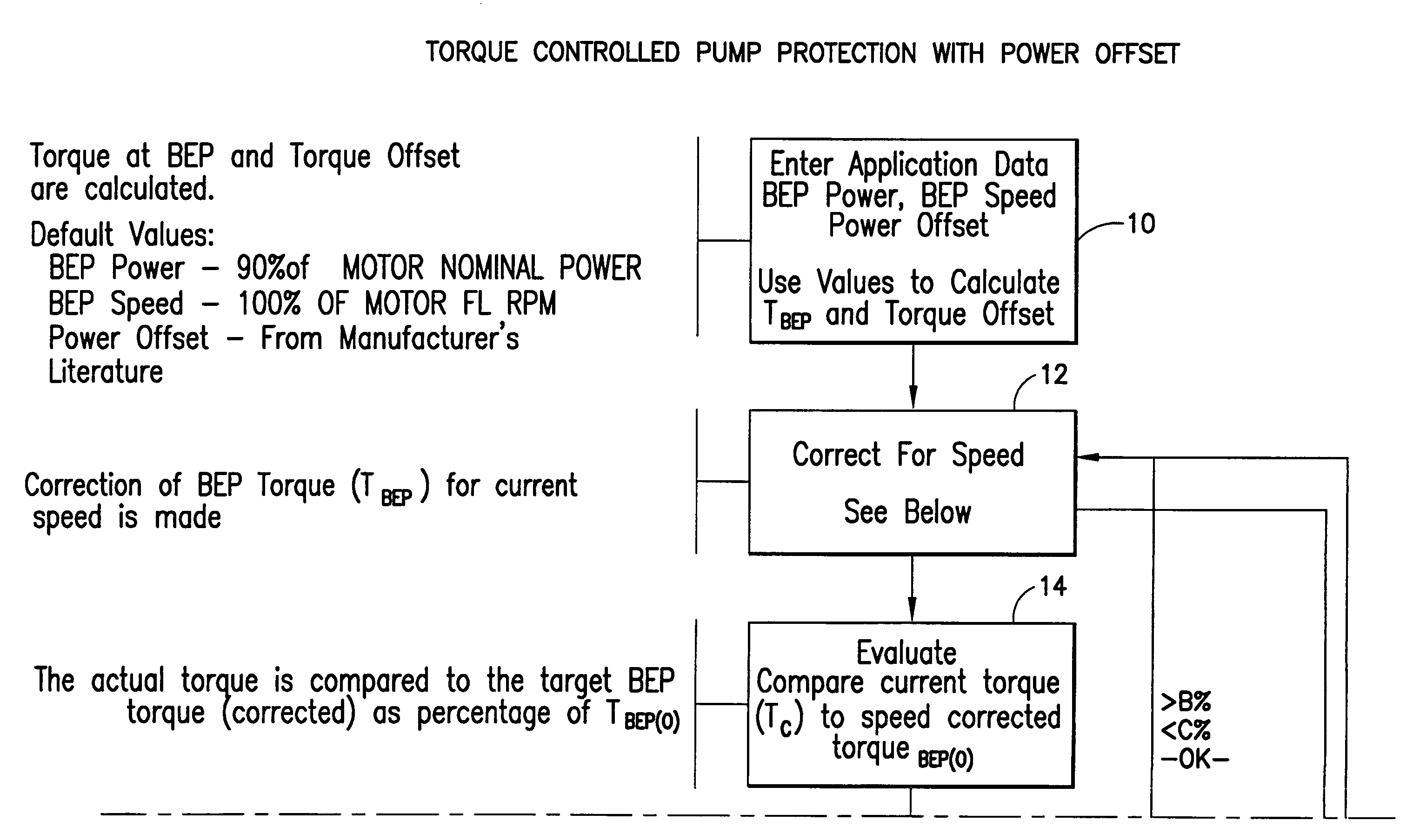
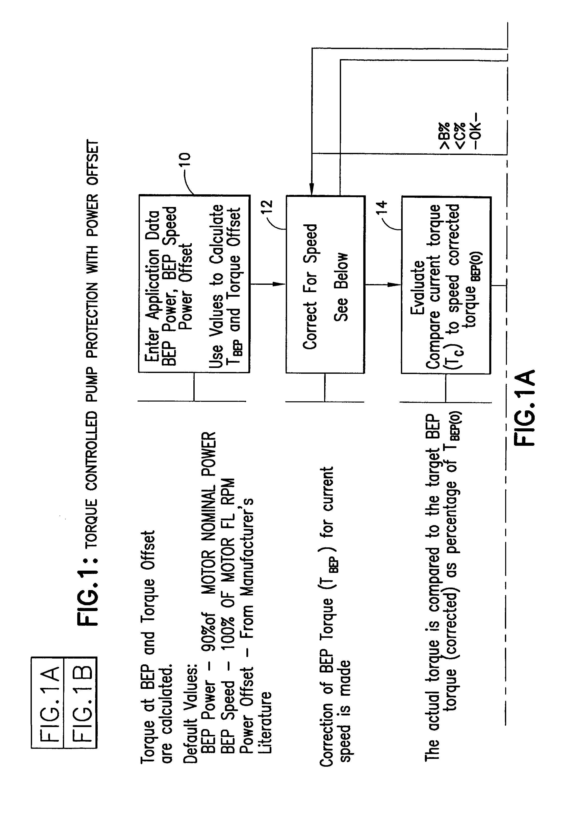
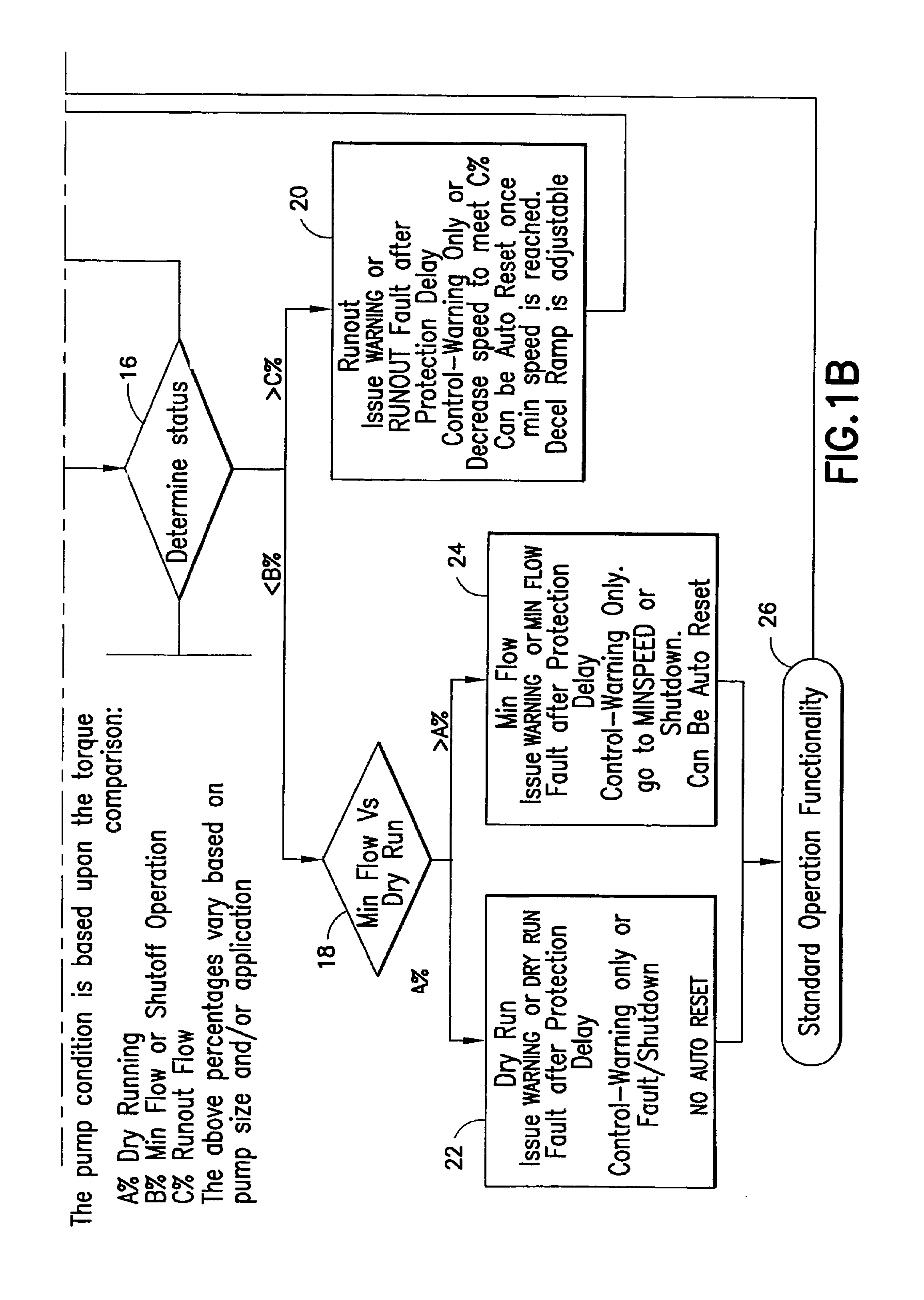
[0030]FIG. 1 shows a flow chart having steps for performing a method according to the present invention for controlling the operation of a pump generally indicated as 100 (FIG. 3), featuring steps of either adjusting the operation of the pump 100, or issuing a warning to a user of the pump 100 of an undesirable operating condition, or both, based on a comparison of an actual torque value and a corrected torque value. The steps of the method are performed by a controller 102 of the pump 100 and motor 103 shown in FIGS. 3 and 4. The invention is described in relation to a pump, although the scope of the invention is intended to include a centrifugal pump or other centrifugal device, such as a blower, mixer or other suitable centrifugal device.

Step 10 for Entering Application Data

[0031]In operation, the controller 102 has an enter application data module 102a (FIG. 4) that first performs a step 10 for entering application data, including entering default values for the BEP power (90% o...


PUM


Abstract

A method and apparatus are provided for controlling the operation of a pump, such as a centrifugal pump, featuring steps of either adjusting the operation of the pump, or issues a warning to a user of the pump of an undesirable operating condition, or both, based on a comparison of an actual torque value and a corrected torque value either alone or in combination with a further step of compensating the corrected torque value based on a mechanical power offset correction. The corrected torque value may include a Best Efficiency Point (BEP) torque value and may also be compensated for based on at least the current operating speed of the pump. The pump has a controller for performing the steps of the method. The controller can compensate the corrected torque value based on the square of the speed change of the pump. The comparison may include a ratio of the actual torque value to the corrected torque value.

Description

BACKGROUND OF THE INVENTION[0001]1. Field of Invention[0002]The present invention relates to a method and apparatus for controlling the operation of a pump, such as a centrifugal pump.[0003]2. Description of Related Art[0004]Many known Variable Frequency Drive (VFD) systems create accurate mathematical models of the motors being driven in order to provide precise control over speed and torque, which are used for controlling the operation of pumps. Such known methods and devices include the following:[0005]U.S. Pat. No. 6,591,697 discloses a pump regulating technique based on a relationship of torque and speed versus the pump flow rate and the ability to regulate the pump flow using a Variable Frequency Drive (VFD) to adjust the centrifugal pump speed. However, this technique does not include logic that would provide for protection against undesirable operating conditions, such as a dry run condition, a minimum flow condition, a runout condition, or some combination thereof. Instead,...

Claims


Application Information

Patent Timeline
Patent Type & Authority Patents(United States)
IPC IPC(8): F04B49/00F04D15/00F04D15/02F16H61/26
CPCF04D15/0254F04D15/0066F04B2201/1202F04B49/00F16H61/26
Inventor STAVALE, ANTHONY E.GANZON, NICOLAS W.KERNAN, DANIEL J.
Owner ITT MFG ENTERPRISES LLC
Why Eureka
Try Eureka