

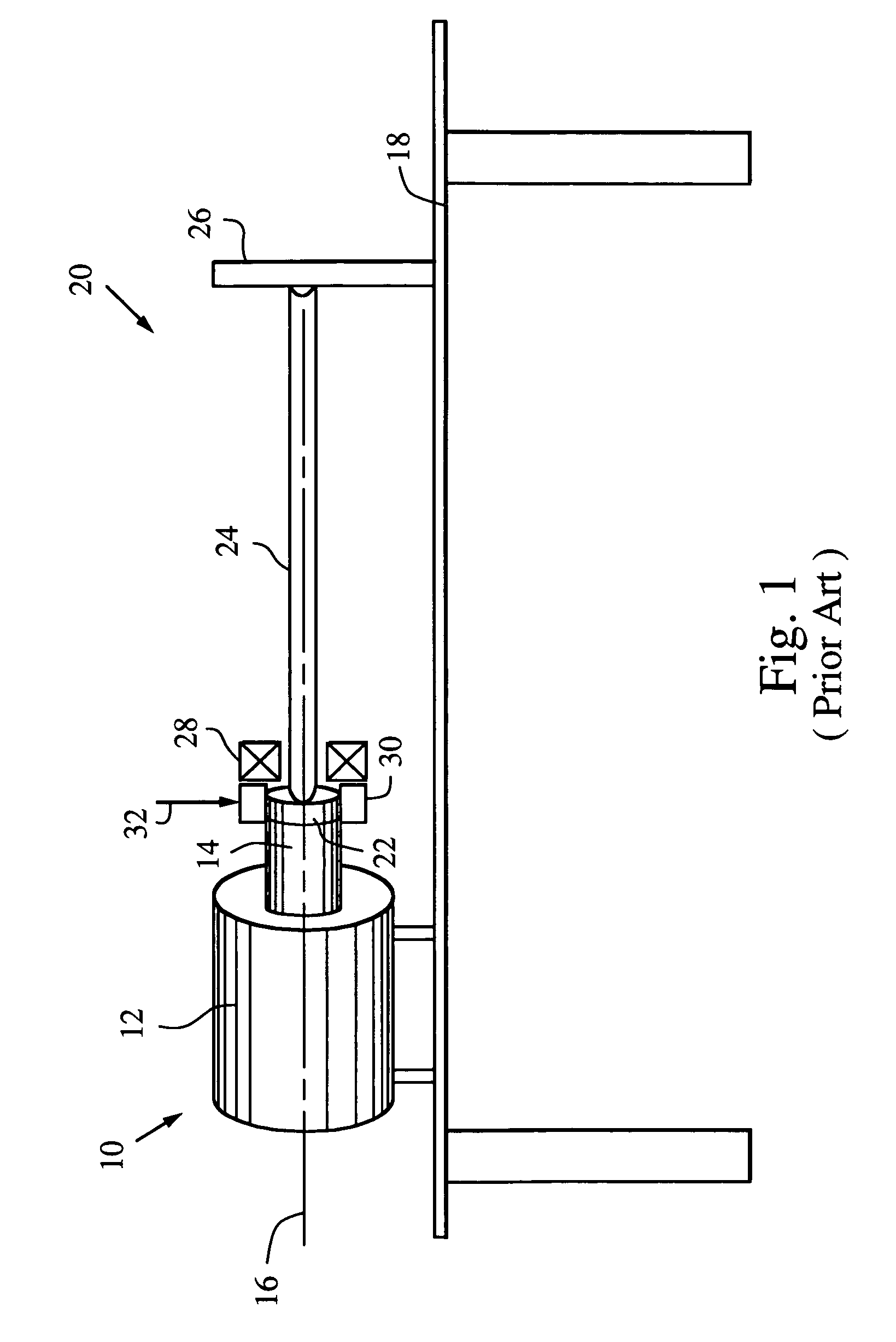
Dynamic load fixture for rotary mechanical systems
a technology of dynamic load fixture and rotary mechanical system, which is applied in the direction of machine part testing, structural/machine measurement, instruments, etc., can solve the problems of affecting the accuracy of encoder measurement, damage to encoder or torsion bar, etc., and achieves high response bandwidth and effective reproduction
- Summary
- Abstract
- Description
- Claims
- Application Information
AI Technical Summary
Benefits of technology
Problems solved by technology
Method used
Image

Examples
Embodiment Construction
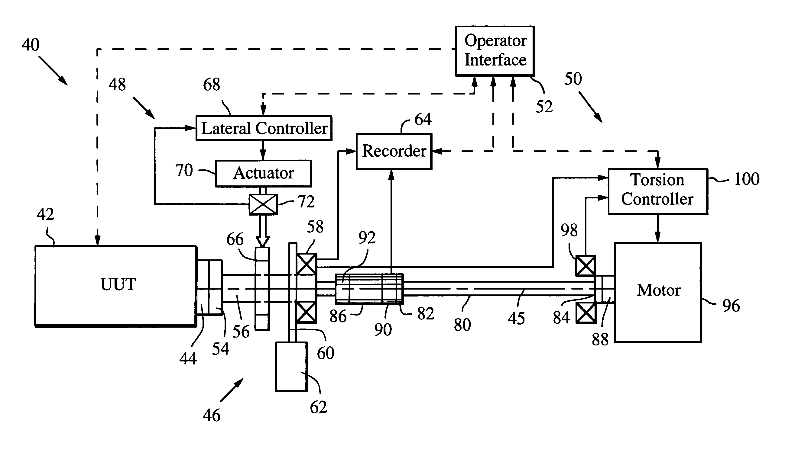
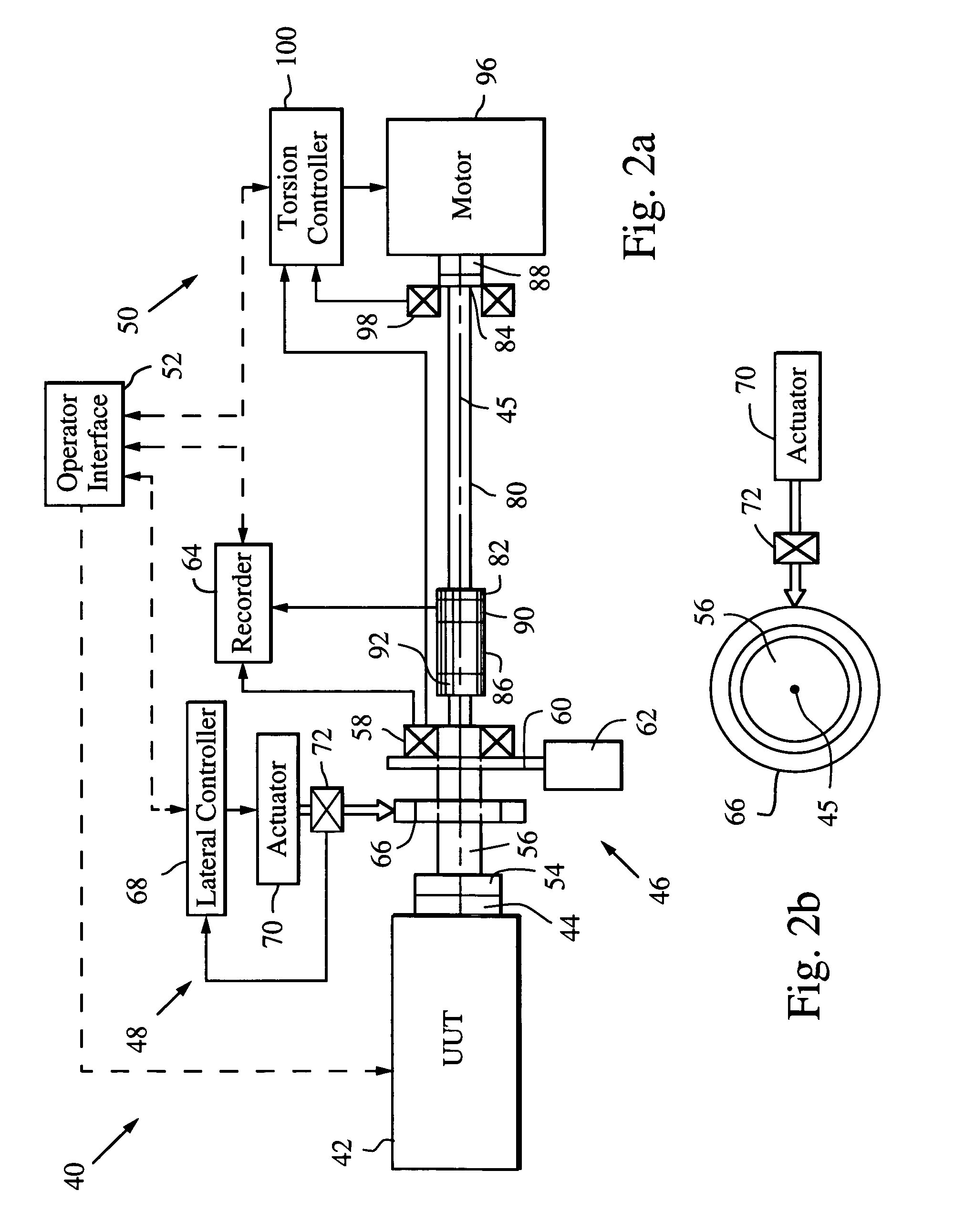
[0024]The present invention provides a dynamic load fixture (DLF) for applying a programmable time-varying lateral load to a rotary mechanical system and isolating the measurement of the angular displacement of its rotational output under load. Although the DLF may be configured to apply no torsion load by leaving the opposite end of the torsion bar free to rotate or removing the torsion bar, or to apply a torsion load that is proportional to the amount of rotation by fixing the end of the torsion bar, the DLF will be described in a configuration in which both dynamic lateral and torsion loads are applied. This configuration allows the DLF to more effectively reproduce desired acceptance tests and real life conditions.
[0025]As shown in FIGS. 2a and 2b, a dynamic load fixture (DLF) 40 is configured for testing a unit under test (UUT) 42 having a drive shaft 44 that rotates about an x-axis 45 (“roll”). The DLF comprises an encoder system 46 that measures the angular rotation of the dr...
PUM
| Property | Measurement | Unit |
|---|---|---|
| lateral force | aaaaa | aaaaa |
| time | aaaaa | aaaaa |
| torsion stiffness | aaaaa | aaaaa |
Abstract
Description
Claims
Application Information